Timing device

a timing device and timer technology, applied in the direction of thermometers using mean/integrated values, electric winding, instruments, etc., can solve the problems of inconspicuous date stamp printing, relatively short shelf life, and relatively long shelf life, and achieve the effect of convenient observation and handling

Inactive Publication Date: 2005-06-30
CHURCH & DWIGHT CO INC
View PDF37 Cites 5 Cited by
  • Summary
  • Abstract
  • Description
  • Claims
  • Application Information

AI Technical Summary

Problems solved by technology

The shelf life may be relatively short such as a few days or may be relatively lengthy such as a few months.
Quite often, date stamps are printed inconspicuously on the product package.
It is sometimes difficult to read the date stamp and in some cases even to find the date stamp because it may be printed anywhere on the package.
Date stamping is particularly problematic for products which have a relatively long shelf life because such products tend to get stored in obscure recesses of a storage area, such as a food cabinet or refrigerator.
If the product is not used often, the consumer is often unaware that the expiration date is shortly forthcoming or has even passed.
The timing indicators mentioned above suffer from one or more disadvantages which makes their universal applicability to a wide range of packaged products problematical.
Such disadvantages include a) the timing mechanism is part of the product (e.g. a deodorizer) and is therefore limited to employment with that product or that class of products, b) the timing mechanism is inaccurate or cannot be controlled to accommodate a wide range of product shelf lives, c) the timing mechanism is expensive and / or d) has a limited range of measurement.

Method used


Image

  • Timing device
  • Timing device
  • Timing device

Examples


example 2

[0024] The following composition was prepared.

TABLE 2ComponentOrder of AdditionWt. %Water132.88Methanol264.37Hydroxyethyl cellulose31.31(Natrosol 250 HR CS)SnCl2.2H2O41.31Indigo Carmine50.13

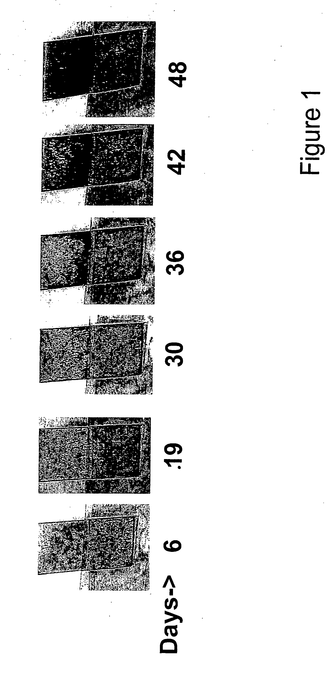
The composition was mixed as in Example 1. A 20 mil film was also drawn and set up for aging employing the procedure set forth in Example 1. Results of the color change are shown in FIG. 2. The color change occurred over a period of about 55±6 days.

example 3

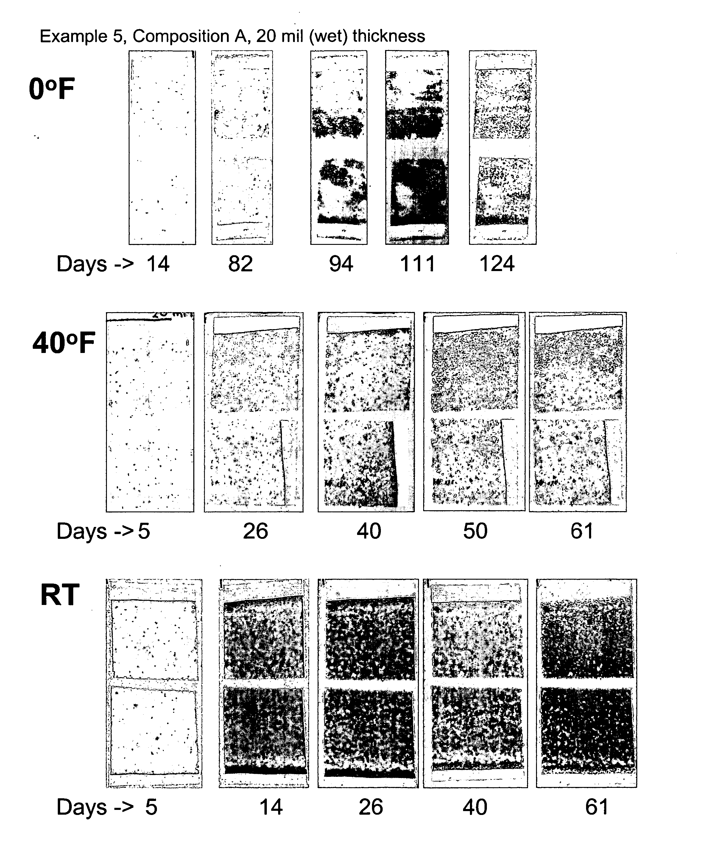
[0025] The film described Example 1 was aged at room temperature (72±3° F.). Results of the color change are shown in FIG. 3. Note the size of the film was about ½″×1″, and that the bottom (covered) half also went through a color change. In this case, it appears that the barrier properties of the adhesive tape were not sufficient to prevent oxygen exposure at room temperature.

[0026] The color change occurred over a period of about 22 to 30 days.

example 4

[0027] The following composition was prepared:

TABLE 3ComponentOrder of AdditionWt. %Water132.88Methanol264.37Hydroxyethyl cellulose31.31(Natrosol 250 HR CS)SnCl2.2H2O41.31Methylene blue50.13

[0028] The mixture was initially blue, but gradually turned whitish-gray. As in Example 1, a film was drawn at a wet thickness of 20 mil. After drying overnight, the film was placed in a refrigerator (40° F.). The bottom half of the film was wrapped in an adhesive film while the top half of the film was exposed to the air. As shown in FIG. 4, the exposed half of the film underwent a color change from white to blue over a period of about 48 days, and continued to darken with a more intense blue up to about 95 days.


PUM

PropertyMeasurementUnit
thicknessaaaaaaaaaa
pHaaaaaaaaaa
pHaaaaaaaaaa

Abstract

A timing device for visually determining the passage of a preselected period of time including a redox indicator and a metal salt wherein the indicator undergoes an observable change in color which is related to the desired preselected period of time.

Description

FIELD OF THE INVENTION [0001] The present invention is directed to a timing device for visually determining the passage of a preselected period of time and is applicable to a wide variety of consumer products, especially products which have an extended shelf or use life and for which it is desirable to know when the product must be replaced or rejuvenated. The timing device can be attached to or incorporated in typical packaging employed for consumer products. BACKGROUND OF THE INVENTION [0002] Consumer products including food products, cleaning products, deodorizers and the like have a shelf life determined by the length of time the components of the product resist change to environmental influences. For example, food products have a given shelf life based on their ability to resist chemical or physical changes due to contact with air, heat and other influences in the environment. Many consumer products are date stamped to provide the user with an indication of the shelf life of th...

Claims


Application Information

Patent Timeline
Patent Type & Authority Applications(United States)
IPC IPC(8): G01K3/04G04C1/00G04F1/06
CPCG04F1/06G01K3/04
Inventor ADAMY, STEVEN T.
Owner CHURCH & DWIGHT CO INC
Why Eureka
Try Eureka