
Adaptive modulation and other extensions of the physical layer in multiple access systems

Active Publication Date: 2005-06-30
GIGASET COMMUNICATIONS
View PDF4 Cites 34 Cited by
  • Summary
  • Abstract
  • Description
  • Claims
  • Application Information

AI Technical Summary

Benefits of technology

[0018] Thus, adaptive nodulation also can be applied in multiple access systems; for example, to the CSMA (Carrier Sense Multiple Access) system on the basis of the bit loading signaling scheme specified by the present invention. For adaptive modulation, however, it is absolutely vital for the desired bit loading tables to be transferred correctly from the receiver to the transmitter. If this is not the case, serious faults can occur. Use of the bit loading signaling scheme above all makes it possible to transmit adaptively-modulated data packets which, because of the adaptive modulation, are less susceptible to packet errors.
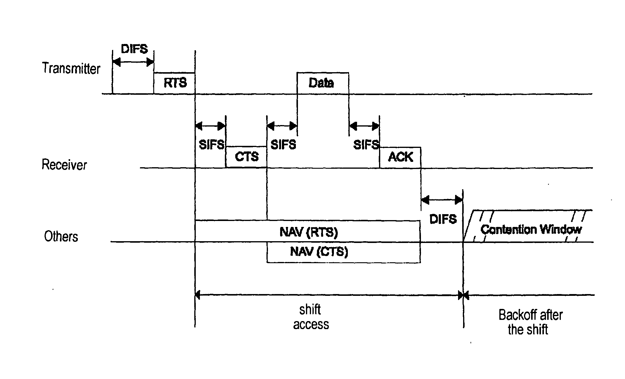
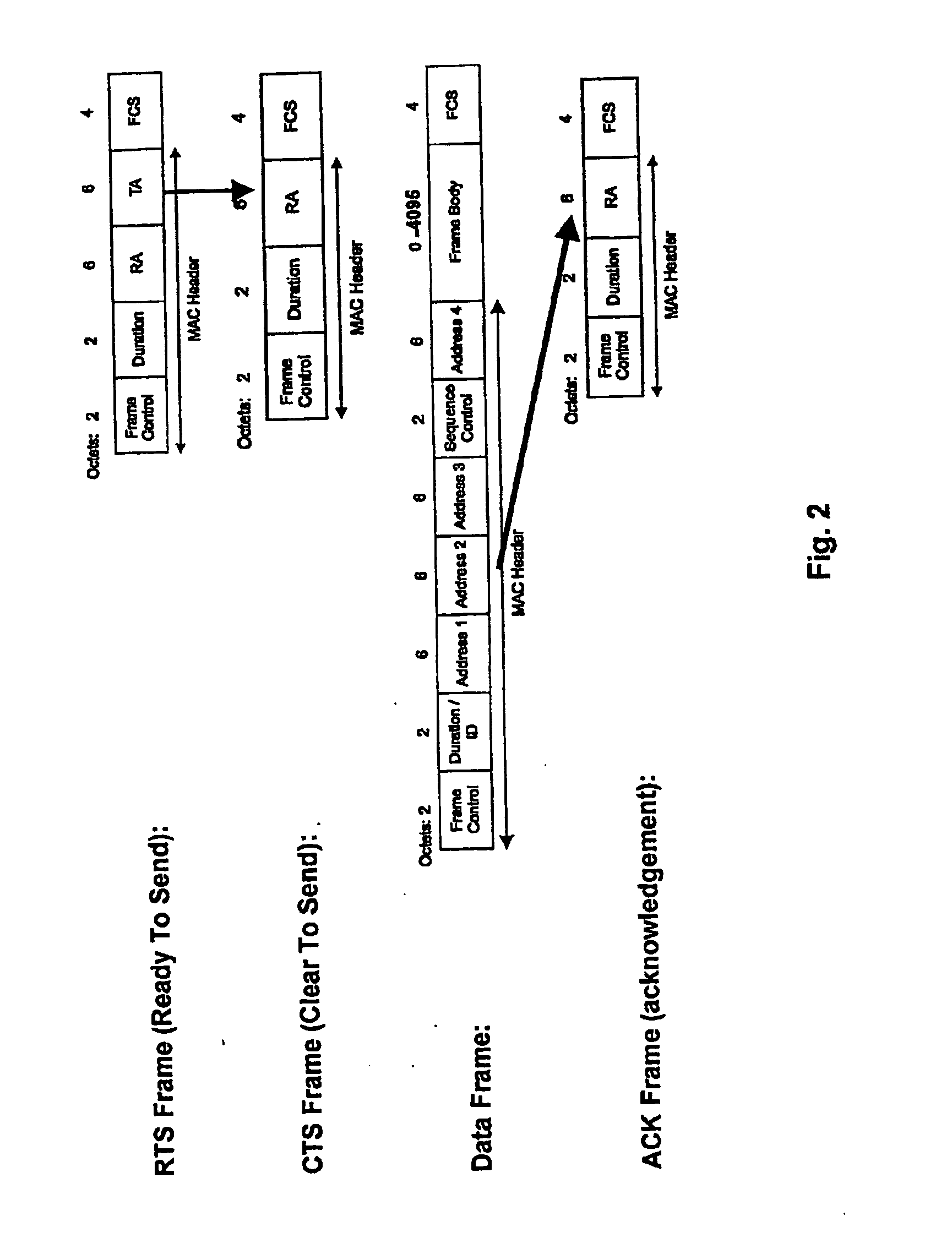
[0020] As already indicated, the method in accordance with the present invention can be used very advantageously for IEEE 802.11-standard systems. In such systems, pilots can be sent for calculating bit loading tables in the RTS signal for distributed access. Furthermore, it is worthwhile for the transmitter to ask the receiver in the RTS signal whether it is capable of adaptive modulation and, where necessary, of executing additional functions, known as the PHY extensions, within the framework of the physical layer.
[0021] In a similar way, it is advantageous for the receiver to ask the transmitter in the CTS signal about the ability to execute adaptive modulation and, where necessary, further PHY extensions. At the same time, the receiver can send the assignment tables or bit loading tables calculated on the basis of the pilots, respectively, in the CTS signal to the transmitter.

Problems solved by technology

If this is not the case, serious faults can occur.

Method used


Image

  • Adaptive modulation and other extensions of the physical layer in multiple access systems
  • Adaptive modulation and other extensions of the physical layer in multiple access systems
  • Adaptive modulation and other extensions of the physical layer in multiple access systems

Examples


Embodiment Construction

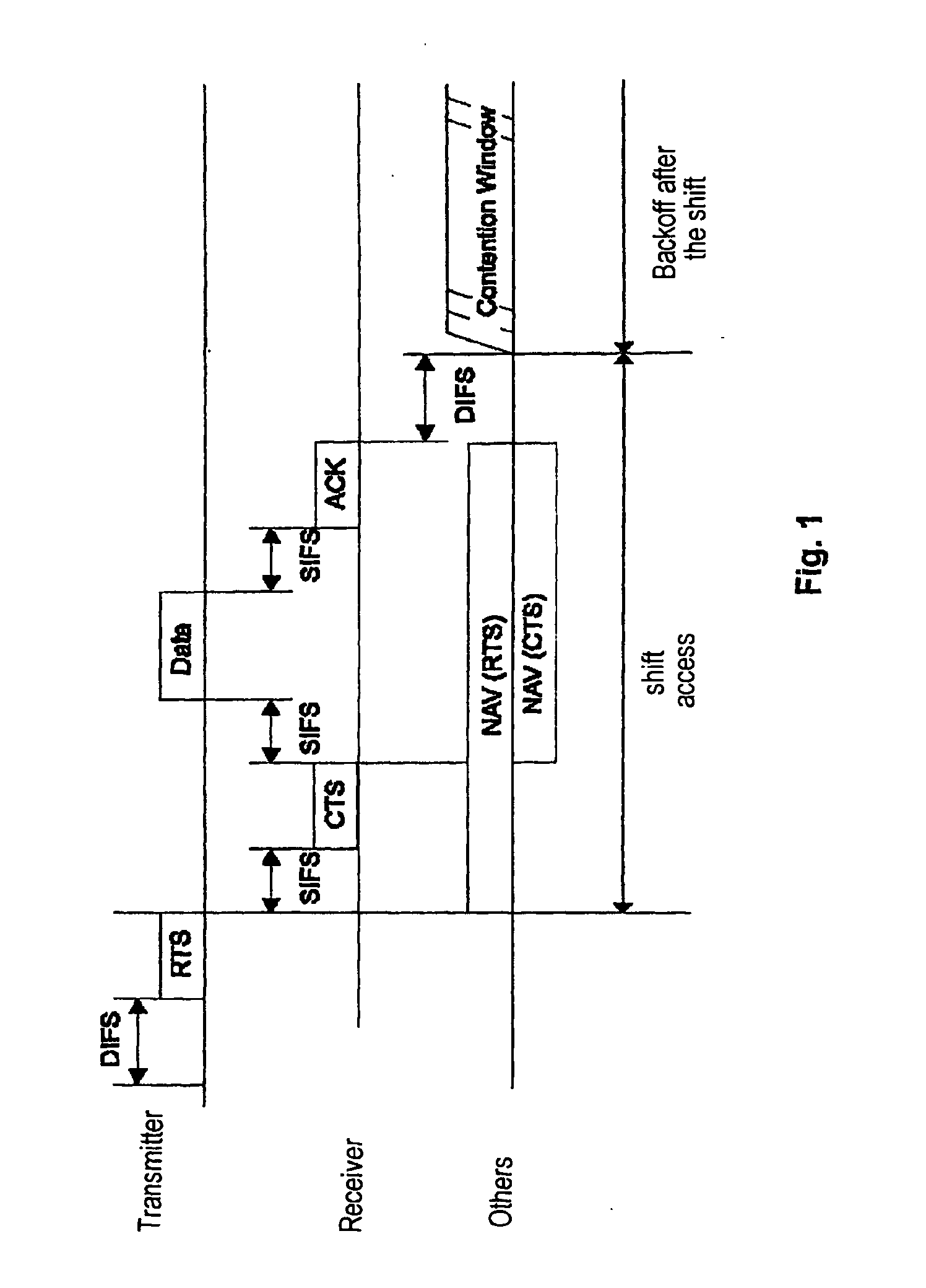
[0035] The fundamentals of the inventive signaling scheme shown in FIG. 3 correspond to those of the scheme shown in FIG. 1 and are thus based on Standard IEEE 802.11. However, as indicated by the thick arrows in FIG. 3, the content of the relevant data frame has been changed. To perform adaptive modulation an inquiry is made in the RTS signal of the transmitter about a bit loading table of the receiver. The receiver, in turn, integrates into its CTS message the bit loading table which it has calculated on the basis of pilots of the RTS signal. The bit loading table received by the transmitter in the CTS message is used by the transmitter to send the data in the data packet “Data.”

[0036] A second signaling scheme is indicated by the thin arrows in FIG. 3. In this scheme, the receiver requests a bit loading table from the transmitter in a CTS message. The latter calculates a current bit loading table for the forwards channel on the basis of pilots from the CTS signal and integrates t...


PUM


Abstract

The present invention seeks to improve data exchange in a communications system that is especially standardized according to IEEE 802.11a. For this purpose, when the transmission medium, preferably an IEEE 802.11 system with a distributed coordination function (DCF) is accessed in a decentralized manner, pilot signals are transmitted from the transmitter to the recipients using a number of transmission modes and then an allocation table regarding the transmission modes is calculated by the recipient on the basis of the pilot symbols received. The recipient transmits the allocation table to the transmitter so that the subsequent data exchange can proceed on the basis of the allocation table. In the case of centralized access, preferably an IEEE 802.11 system with a point coordination function (PCF), data exchange is improved in that the subsequent data are adaptively modulated already when the allocation table is transmitted.

Description

BACKGROUND OF THE INVENTION [0001] The present invention relates to a method of transmitting data signals in a communication system with access to the transmission medium organized on a central or distributed basis using a number of transmission modes. In particular the present invention relates to a signaling scheme for adaptive modulation in a CSMA / CA (Carrier Sense Multiple Access Collision Avoidance) IP-based access system. [0002] A serious problem in mobile radio transmission is the frequency selectivity of the mobile radio channels. The frequency selectivity, generated by multipath propagation with large delay time differences, causes heavily linear distortions of the receive signal, which makes it necessary to use expensive equalizers or to use Viterbi detection. A suitable way of combating the disadvantages of frequency selective channels is what is known as Adaptive Modulation (AM), which is described in greater detail below. [0003] Adaptive Modulation is used in OFDM (Orth...

Claims


Application Information

Patent Timeline
IPC IPC(8): H04L1/02H04L12/28
CPCH04W74/0808H04L12/28
Inventor BOLINTH, EDGARKERN, RALF
Owner GIGASET COMMUNICATIONS
Learn More