Temperature sensing oscillator circuit
- Summary
- Abstract
- Description
- Claims
- Application Information
AI Technical Summary
Benefits of technology
Problems solved by technology
Method used
Image

Examples
Embodiment Construction
[0023] The present invention will be described in detail with reference to the accompanying drawings.
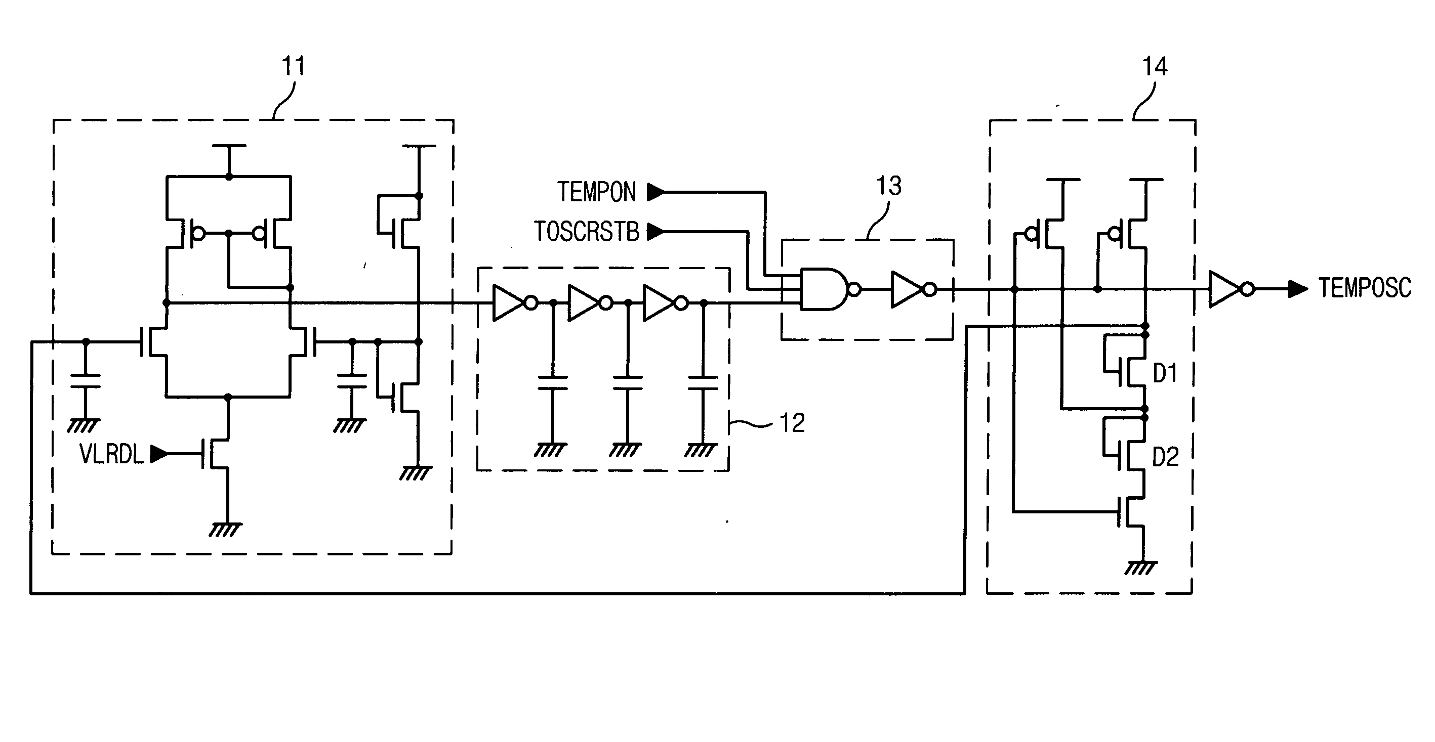
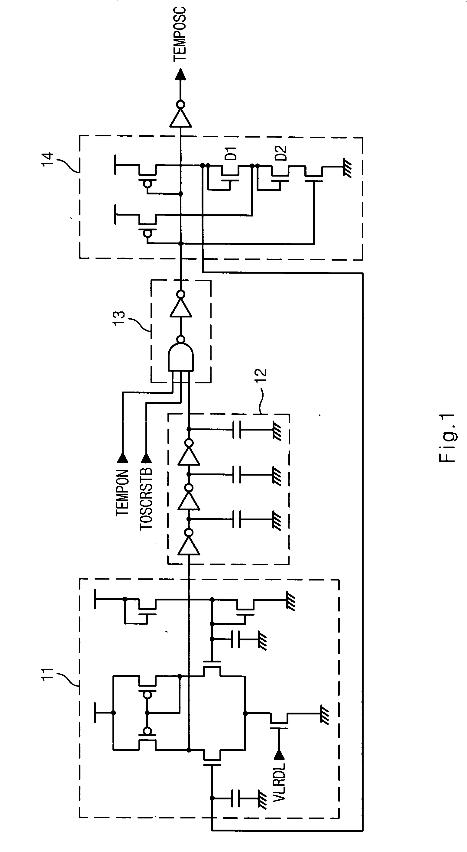
[0024]FIG. 3 is a circuit diagram of a temperature sensing oscillator circuit according to an embodiment of the present invention.
[0025] The temperature sensing oscillator circuit of FIG. 3 comprises a temperature sensing pulse generating unit 20, a pulse width regulating unit 30 and a buffer unit 40.
[0026] The temperature sensing pulse generating unit 20 outputs a pulse signal having a cycle varied by changing an operating power depending on temperature change. The temperature sensing pulse generating unit 20 comprises a variable power supply unit 22 and a ring oscillator 24.
[0027] The variable power supply unit 22 variably supplies a operating power of the ring oscillator 24 depending on temperature change. The variable power supply unit 22 comprises a diode-connected PMOS transistor P1 connected between a power voltage terminal VDD and the ring oscillator 24. In other words, i...
PUM
 Abstract
Description
Claims
Application Information
 - Generate Ideas
- Intellectual Property
- Life Sciences
- Materials
- Tech Scout
- Unparalleled Data Quality
- Higher Quality Content
- 60% Fewer Hallucinations
Browse by: Latest US Patents, China's latest patents, Technical Efficacy Thesaurus, Application Domain, Technology Topic, Popular Technical Reports.
© 2025 PatSnap. All rights reserved.Legal|Privacy policy|Modern Slavery Act Transparency Statement|Sitemap|About US| Contact US: help@patsnap.com