
Image compressor for generating predicted difference code having fixed bit length and program thereof, image decompressor for decoding the code and program thereof, and electronic camera

a technology of image compressor and predicted difference, which is applied in the field of image compressor, can solve the problems of large amount of data for each frame, difficult to increase the number of frames taken by high-speed continuous shooting, and the amount of data after compression is not necessarily constant, so as to reduce the degradation of image quality

Active Publication Date: 2005-06-30
NIKON CORP
View PDF3 Cites 21 Cited by
  • Summary
  • Abstract
  • Description
  • Claims
  • Application Information

AI Technical Summary

Benefits of technology

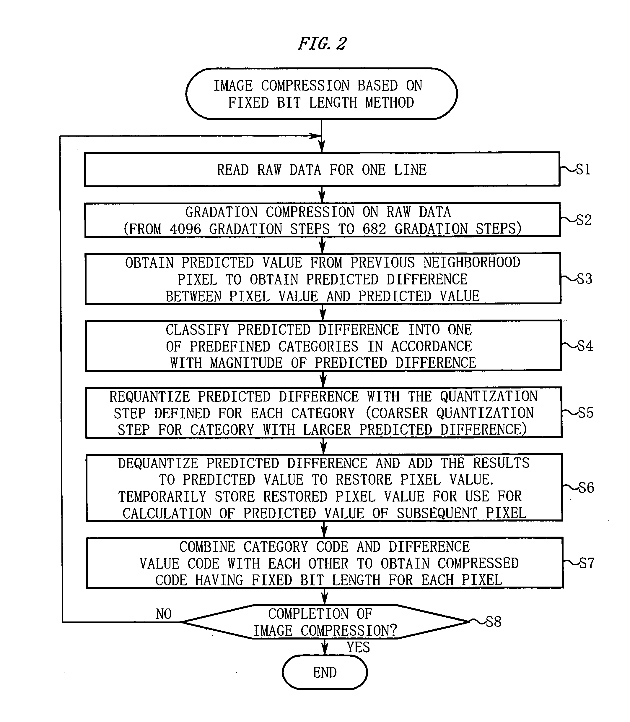
The present invention provides an image compression technique with reduced degradation in image quality. This is achieved by using a difference calculating unit and a difference requantizing unit to apply coarser quantization steps to a predicted difference when the magnitude of the predicted difference exceeds a predetermined threshold value. This results in a bit length of the predicted difference falling within a fixed bit length range, enabling a fixed bit length method with reduced degradation in image quality. Additionally, the invention includes a gradation compression unit to reduce the number of gradation steps, and a compression control unit to switch between compression methods based on the amount of compressed data. The invention also provides an image decompressor for restoring the original image data.

Problems solved by technology

However, since the uncompressed raw data is quantized to have multiple gradation steps (for example, 12-bit quantization), the amount of data for each frame is large.
Accordingly, it is difficult to increase the number of frames taken by high-speed continuous shooting only if the uncompressed raw data is temporarily stored in the buffer memory.
However, according to the variable length encoding, the amount of data after compression is not necessarily constant.
In particular, when the assignment of variable length codes is not appropriate for the raw data, the amount of data after compression becomes unexpectedly large in some cases.
As a result, a disadvantage that a user misses the right moment to release the shutter, which is precious for the user, may arise.
In this manner, it was impossible to certainly ensure the minimum number of frames taken by high-speed continuous shooting if the raw data is variable-length encoded.
In fixed bit length-based encoding, however, it is difficult to sufficiently increase the compression efficiency because a bit length for each pixel is fixed.
If the compression efficiency is forced to be increased, there arises a fundamental problem that the degradation in image quality is increased along with the compression.

Method used


Image

  • Image compressor for generating predicted difference code having fixed bit length and program thereof, image decompressor for decoding the code and program thereof, and electronic camera
  • Image compressor for generating predicted difference code having fixed bit length and program thereof, image decompressor for decoding the code and program thereof, and electronic camera
  • Image compressor for generating predicted difference code having fixed bit length and program thereof, image decompressor for decoding the code and program thereof, and electronic camera

Examples


Embodiment Construction

[0060] Hereinafter, an embodiment of the present invention will be described in detail with reference to the accompanying drawings.

(Description of the Entire Configuration of an Electronic Camera)

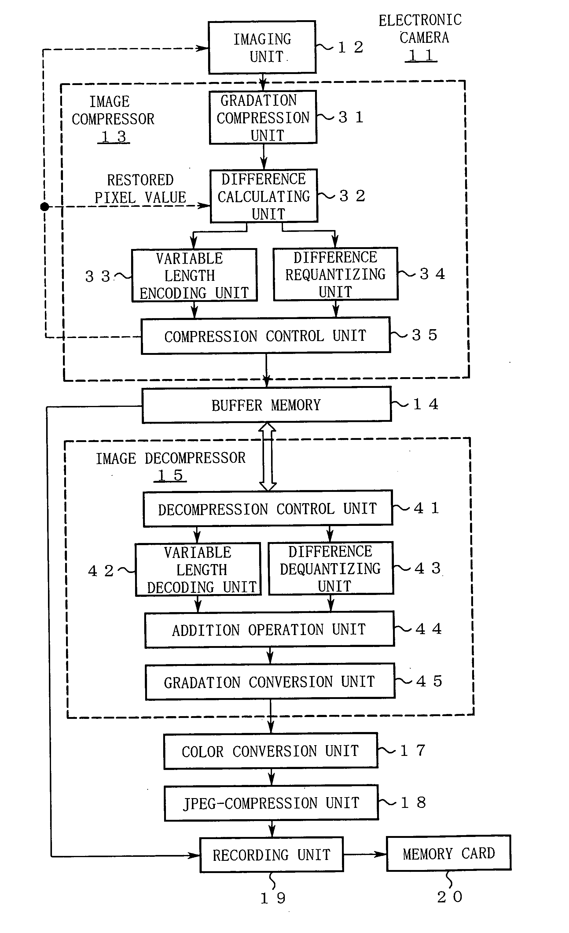
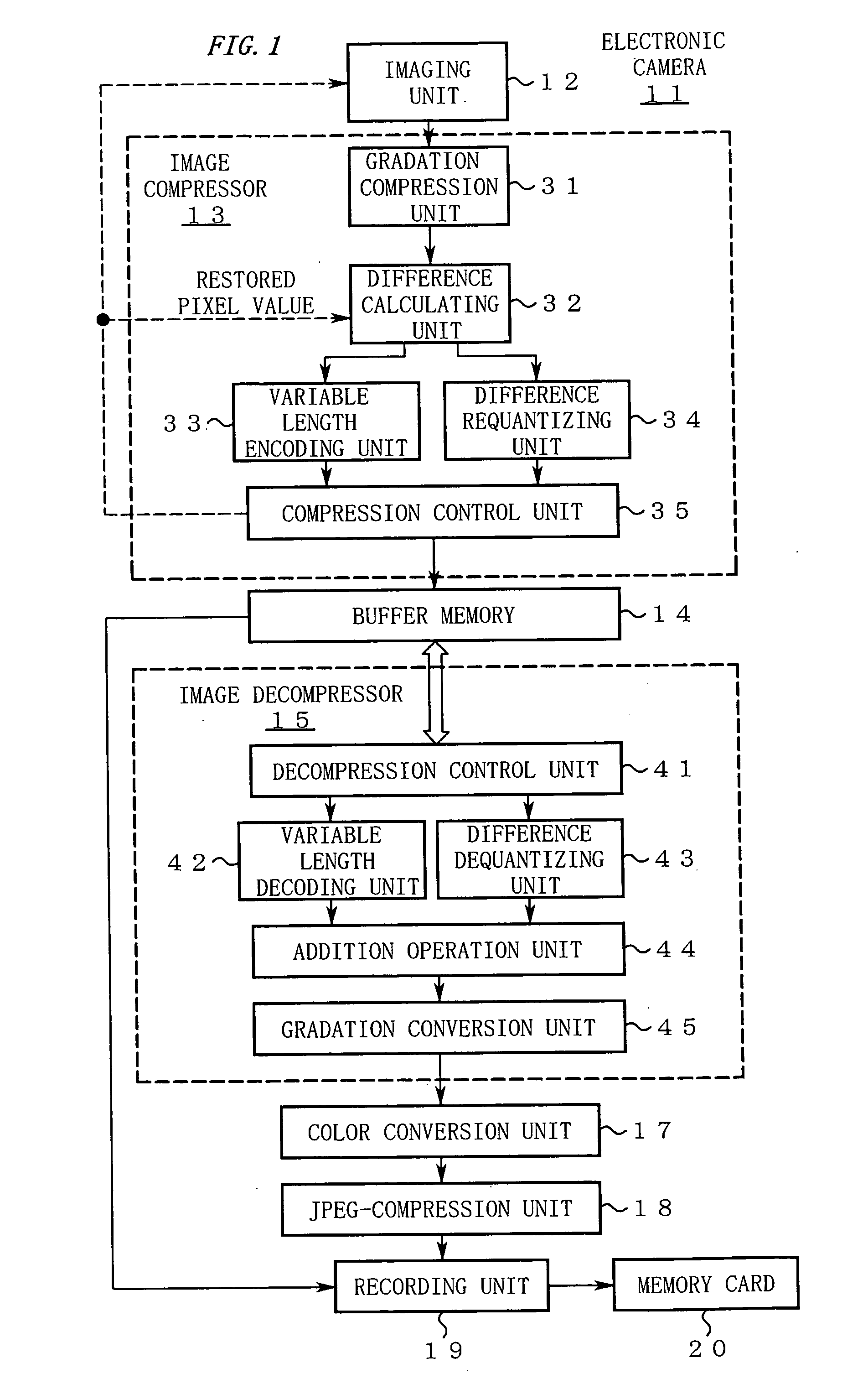
[0061]FIG. 1 shows a structure of an electronic camera 11 according to this embodiment.

[0062] In FIG. 1, the electronic camera 11 includes an imaging unit 12. The imaging unit 12 has a normal shooting function as well as a function of continuously shooting a subject to sequentially output raw data. The thus sequentially output raw data is subjected to image compression in almost real time by an image compressor 13 so as to be sequentially stored in a buffer memory 14 as compressed data.

[0063] An image decompressor 15 reads out the compressed data from the buffer memory 14 at appropriate time for image decompression in accordance with the status of a recording unit 19 at a later stage so as to restore the raw data. The restored raw data passes through a color conversion unit 17, a JPEG-...


PUM


Abstract

An image compressor of the present invention includes a difference calculating unit and a difference requantizing unit. The difference calculating unit calculates a predicted difference between a pixel value of image data and a predicted value (a calculated value of the pixel value predicted from known data). When a magnitude of the predicted difference exceeds a predefined threshold value, the difference requantizing unit applies the coarse quantization steps to requantize the predicted difference to keep a bit range to predetermined size. In this manner, compressed data, in which a bit length of the predicted difference for one pixel is adjusted to a fixed bit length, is generated.

Description

CROSS REFERENCE TO RELATED APPLICATION [0001] The disclosure of the following priority application is herein incorporated by reference: Japanese Patent Application No. 2003-430926, filed on Dec. 25, 2003. BACKGROUND OF THE INVENTION [0002] 1. Field of the Invention [0003] The present invention relates to an image compressor for generating compressed data after adjusting a bit length of a predicted difference for one pixel to a fixed bit length and to an image compression program. [0004] The present invention also relates to an image decompressor for decompressing the compressed data and an image decompression program. [0005] The present invention further relates to an electronic camera including the image compressor described above. [0006] 2. Description of the Related Art [Background Technique of an Electronic Camera][0007] An electronic camera for storing raw data, which is obtained by continuous shooting, in a buffer memory without compression is known as a conventional electron...

Claims


Application Information

Patent Timeline
Patent Type & Authority Applications(United States)
IPC IPC(8): G06T9/00G06K9/36H04N1/413H04N1/417H04N19/126H04N19/136H04N19/137H04N19/196H04N19/30H04N19/50H04N19/91H04N23/40H04N101/00
CPCH04N2101/00H04N19/60H04N19/593H04N19/182H04N19/137H04N19/152H04N19/124
Inventor OKADA, SADAMI
Owner NIKON CORP
Learn More