Micro-fluidic heating system

a heating system and microfluidic technology, applied in the direction of fluid speed measurement, positive displacement liquid engine, chemical vapor deposition coating, etc., can solve the problems of increasing the thermal mass of the element, increasing the processing cost disadvantageously, and complicated fabrication process

Inactive Publication Date: 2005-06-30
ELECTRONICS & TELECOMM RES INST
View PDF8 Cites 134 Cited by
  • Summary
  • Abstract
  • Description
  • Claims
  • Application Information

AI Technical Summary

Benefits of technology

[0013] The upper and lower substrates are formed of a glass, a high molecule, or a metal, and the support member is formed of metal or silicon.
[0014] The lower substrate is formed to have a thickness of 1 μm to 100 μm, and the membrane is formed of a silicon nitride layer, a silicon oxide layer, or a synthetic high molecular material and has a thickness of 0.1 μm to 20 μm.

Problems solved by technology

As a result, a processing cost disadvantageously becomes increased.
However, as the heating function is included in the micro-fluidic element for single use, which causes its fabrication process to be complicated.
Furthermore, the thermal plate is fabricated by a conventional machine processing method, so that the element has an increased thermal mass due to the thickness and size of its thermal plate, which fails to have fast heating and cooling speeds compared to the element fabricated by a surface micromachining process.

Method used


Image

  • Micro-fluidic heating system
  • Micro-fluidic heating system
  • Micro-fluidic heating system

Examples


first embodiment

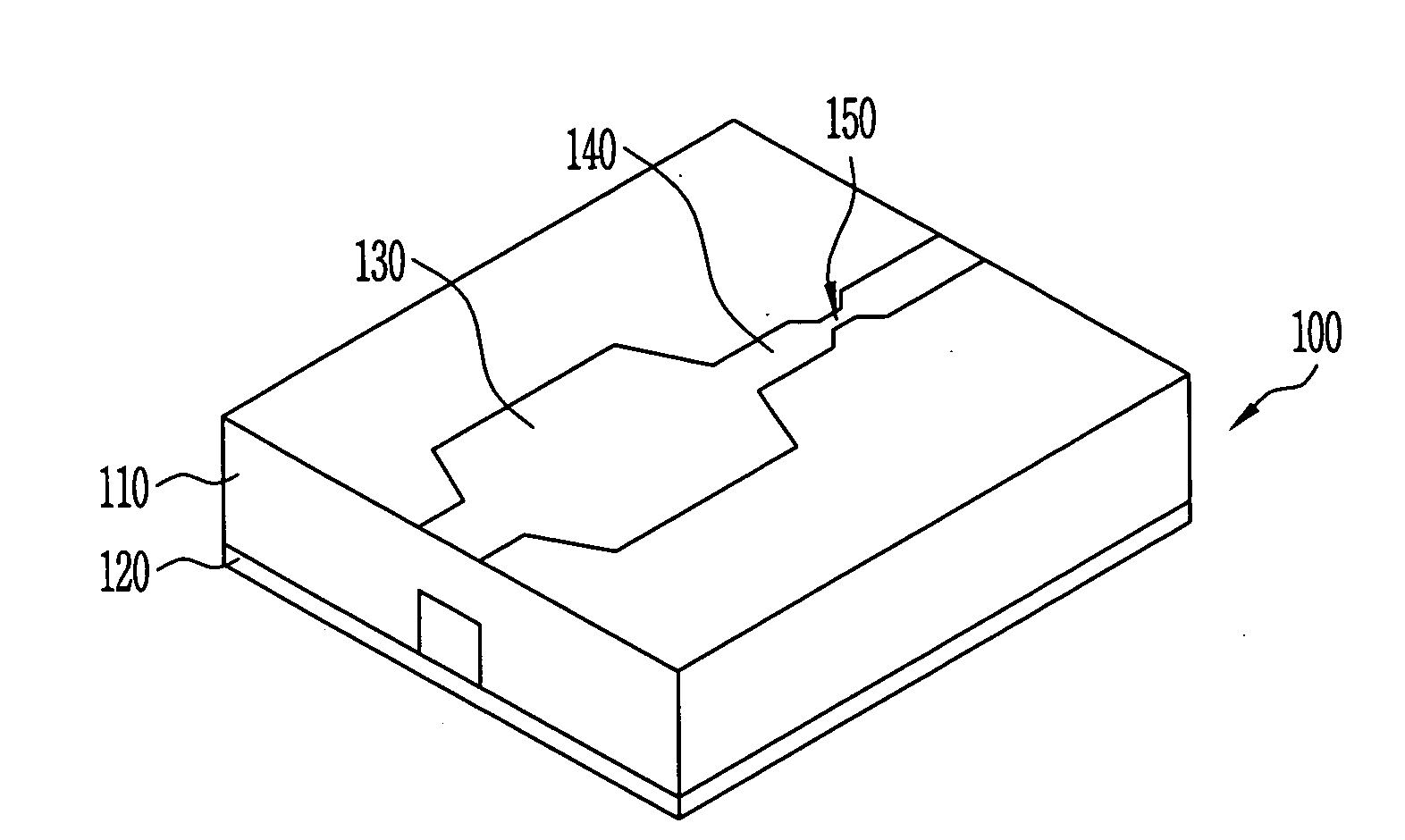
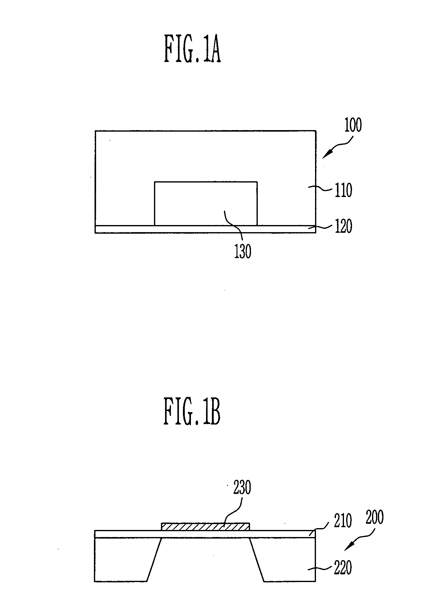
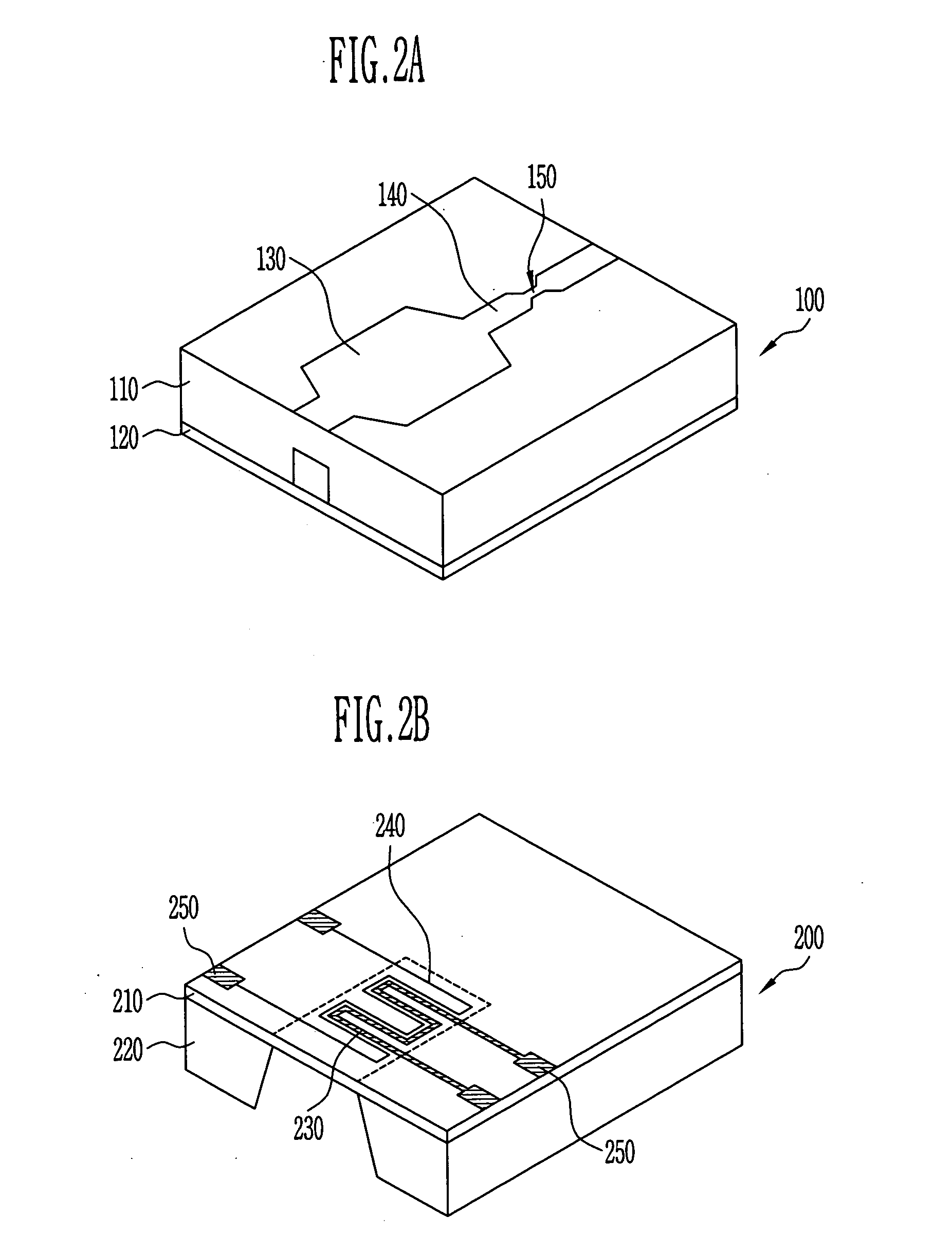
[0024] The micro-fluidic heating system in accordance with the present invention comprises a micro-fluidic control element for providing a chamber, a flow path and a valve, and a main body for heating the chamber and connected to the micro-fluidic control element. FIG. 1A and FIG. 2A show the micro-fluidic control element, and FIG. 1B and FIG. 2B show the main body.

[0025] Referring to FIG. 1A and FIG. 2A, the micro-fluidic control element 100 is comprised of an upper substrate 110 and a lower substrate 120. The upper substrate 110 has a chamber 130, a flow path 140 for transporting the micro fluid to the chamber 130 and so forth formed in a negative pattern. The flow path 140 may have a valve 150 for controlling flow of the micro fluid to be transported. The lower substrate 120 is bonded to the upper substrate 110 so as to shield the chamber 130, the flow path 140, and the valve 150.

[0026] Any material such as a glass, a high molecule, or a metal may be employed for the upper subst...

second embodiment

[0034] The micro-fluidic heating system in accordance with the present invention comprises a micro-fluidic control element for providing a plurality of chambers, a flow path and a valve, and a main body for heating each chamber and in contact with the micro-fluidic control element. FIG. 3A and FIG. 4A show the micro-fluidic control element, and FIG. 3B and FIG. 4B show the main body.

[0035] Referring to FIG. 3A and FIG. 4A, the micro-fluidic control element 300 is comprised of an upper substrate 310 and a lower substrate 320. The upper substrate 310 includes a plurality of chambers 330-1 to 300-n arranged in array, and a plurality of flow paths for micro-fluidic transport connected to both ends of each chamber 330-1 to 300-n, which are formed in a negative pattern. The valve 350 for controlling flow of the micro-fluid may be formed in each flow path 340. The lower substrate 320 is bonded to the upper substrate 310 so as to shield the chambers 330-1 to 330-n, the flow path 340, and th...

third embodiment

[0041]FIG. 5 is a cross sectional view for illustrating a micro-fluidic heating system in accordance with the present invention.

[0042] The micro-fluidic heating system in accordance with the third embodiment of the present invention may applied to structures of both of the first and second embodiments. To detail this, a cooling plate 260 is attached below the support member 220 or 420 of the main body 100 or 200. The temperature of the support member 220 or 420 for supporting the main body 100 or 200 using the cooling plate 260 is maintained at or below a room temperature, so that the chamber 130 or 330 may be cooled in a short time. The cooling plate 260 may be fabricated with metal having a high thermal transfer coefficient, and a water cooling tube may be formed inside of the cooling plate so as to perform partial cooling.


PUM

PropertyMeasurementUnit
thicknessaaaaaaaaaa
thicknessaaaaaaaaaa
thicknessaaaaaaaaaa

Abstract

Provided is a micro-fluidic heating system, which comprises a micro-fluidic control element for providing a chamber, a flow path and a valve, and a main body for heating the inside of the chamber in contact with the micro-fluidic control element, wherein the micro-fluidic control element consists of an upper substrate for providing the chamber, the flow path and the valve, and a lower substrate as a thin film bonded to the upper substrate, and the main body consists of a membrane in which heating means and suction holes are formed, and support member for supporting the membrane, and the heating means is partially in contact with the lower substrate of the chamber to heat the inside of the chamber, so that thermal transfer efficiency becomes maximized and temperature of each chamber may be independently controlled in the case of configuration having chambers arranged in array.

Description

BACKGROUND [0001] 1. Field of the Invention [0002] The present invention generally relates to a micro-fluidic heating system applied in a micro automatic analysis system, and more particularly, to a micro-fluidic heating system that can be fabricated with a low cost and can be used as disposable applications and has fast heating and cooling speeds. [0003] 2. Discussion of Related Art [0004] In general, a micro automatic analysis system such as a bio sensor, a bio chip, a High Throughput Screening (HTS) system, and a combinatory chemistry system requires a micro-fluidic control system having a heating function. Such a micro-fluidic control system requires a function of heating or cooling a single chamber or a plurality of chambers within the system in a short time. [0005] To that end, methods for forming multi-layered flow patterns and integrating a plurality of chambers and heaters within a micro-fluidic control element have been researched (See U.S. Pat. No. 6,572,830; 3 Jun., 2003...

Claims


Application Information

Patent Timeline
Patent Type & Authority Applications(United States)
IPC IPC(8): B81B1/00B01L3/00B01L7/00B81C1/00C40B60/14H05B3/26
CPCB01J2219/00286H05B2203/017B01J2219/00495B01J2219/00783B01J2219/00822B01J2219/00831B01J2219/00833B01J2219/00869B01J2219/00873B01L3/502707B01L7/00B01L2300/1827C40B60/14H05B3/26H05B2203/003H05B2203/013B01J2219/00389B81B1/00
Inventor KIM, SUNG JINYANG, HAE SIKLEE, DAE SIKLIM, YONG TAIKCHUNG, KWANG HYOKIM, KYU WONPARK, SE HOKIM, YUN TAE
Owner ELECTRONICS & TELECOMM RES INST
Why Eureka
Try Eureka