
Reagent container

a technology of reagents and containers, applied in the field of reagent containers, can solve the problems of limited flexibility in selecting combinations of reagents, unskilled operators performing those operations, and large burden on operators, and achieve the effect of increasing flexibility in selecting combinations and easing the selection process

Inactive Publication Date: 2005-06-30
HITACHI HIGH-TECH CORP
View PDF6 Cites 34 Cited by
  • Summary
  • Abstract
  • Description
  • Claims
  • Application Information

AI Technical Summary

Benefits of technology

The present invention provides a reagent container for automatic analysis in an automatic analyzer. The reagent container has a joint portion that allows two or more reagent containers to be directly jointed together. The sum of lengths of the reagent containers in the jointed state is substantially constant, which allows for easy placement of the reagent containers in proper combinations regardless of the operator's knowledge. The reagent container also increases flexibility in selecting combinations of the reagents. The sealable opening of the reagent container allows for easy storage and preserves the reagents. The reagent container can be easily set up and used in the automatic analyzer.

Problems solved by technology

In a-clinical test for analyzing a component contained in a biological sample, two or more kinds of reagents are usually employed because it is difficult to perform the analysis by using one kind of reagent.
Operations required for managing and preparing reagents can be performed without problems when a dedicated operator is in charge of those operations, but a difficulty arises when an unskilled operator performs those operations.
Also, in the case of setting many measurement items, a large number of reagent containers must be placed in the reagent storage, thus resulting in a large burden exerted on the operator and poor space efficiency.
However, because the known reagent container has a structure of the type inserting a reagent bottle in a dedicated holder and fitting a cap on the holder, there is a limit in flexibility in selecting combinations of reagents.

Method used


Image

  • Reagent container
  • Reagent container
  • Reagent container

Examples


first embodiment

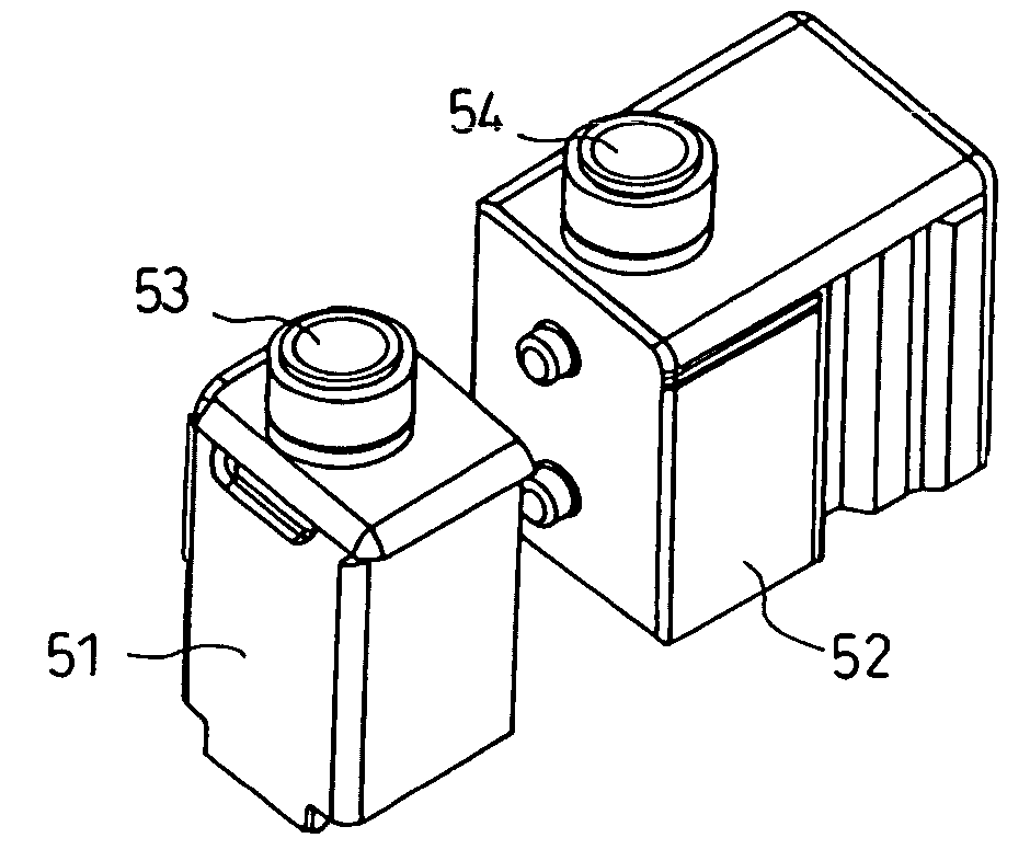
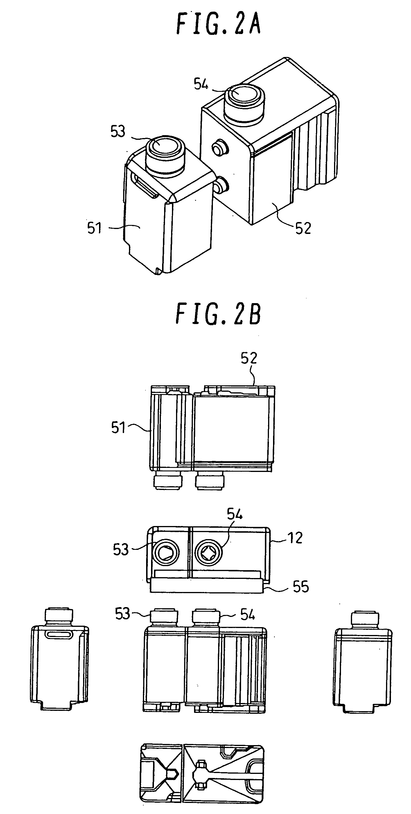
[0038]FIGS. 2A and 2B show the first embodiment of the reagent container for the automatic analyzer according to the present invention.

[0039] The reagent cassette 12 is placed on the reagent disk 26. Referring to FIGS. 2A and 2B, a first reagent container 51 is provided with recesses or projections formed in its side surface, and a second reagent container 52 is provided with projections or recesses formed in its side surface. The recesses or projections of the first reagent container 51 and the projections or recesses of the second reagent container 52 can be jointed to each other in a not easy separable manner in such a state that the relative positional relationship between the first reagent container 51 and the second reagent container 52 is fixedly held. Also, the reagent cassette 12 comprising the first and second reagent containers in the jointed state has outer dimensions defined such that the reagent cassette 12 can be placed in a reagent cassette holder on the reagent dis...

second embodiment

[0047]FIGS. 3A and 3B show the second embodiment of the reagent container for the automatic analyzer according to the present invention.

[0048] A first reagent container 51 and a second reagent container 52 both constituting a reagent cassette 12 are the same as those shown in FIGS. 2A and 2B. A reinforcement member 56 is disposed over upper surfaces of the first reagent container 51 and the second reagent container 52. The reinforcement member 56 serves to not only reinforce the joint between the first reagent container 51 and the second reagent container 52, but also to exactly define the outer dimensions of the reagent cassette and to increase accuracy in positioning of the openings 53, 54 of the first reagent container 51 and the second reagent container 52. While FIG. 3 shows the case in which the reinforcement member 56 is disposed over the upper surfaces of the first reagent container 51 and the second reagent container 52, a reinforcement member may be disposed at bottom por...

third embodiment

[0049]FIGS. 4A and 4B show the third embodiment of the reagent container for the automatic analyzer according to the present invention.

[0050] This third embodiment comprises a first reagent container 51, a second reagent container 52, and a container holder 57, which cooperatively constitute a reagent cassette 12. Neither recesses nor projections used for jointing are provided in or on side surfaces of the first reagent container 51 and the second reagent container 52, and both the reagent containers are held together by the container holder 57. The container holder 57 serves to not only hold both the reagent containers together, but also to exactly define the outer dimensions and the positions of the openings 53, 54 when the first reagent container 51 and the second reagent container 52 are held together. A boss 58 is provided on a part of a side surface of the first reagent container or the second reagent container. The presence of the boss 58 is effective in defining the insert ...


PUM

PropertyMeasurementUnit
lengthsaaaaaaaaaa
heightsaaaaaaaaaa
recessed shapeaaaaaaaaaa

Abstract

A reagent container used for automatic analysis in an automatic analyzer, which enables reagents to be set with ease and which can increase flexibility in selecting combinations of the reagents. In an automatic analyzer for analyzing components of a biological sample by using two or more kinds of reagents, reagent containers containing the two or more kinds of reagents are jointed into one reagent cassette with the aid of a recess and a projection provided in and on the reagent containers, a reagent holder, bonding, tape binding, etc. Thus, a plurality of reagents used for one analysis item are combined with each other in one cassette corresponding to one analysis item. A reagent container for use in automatic analysis, which is easy to handle and highly flexible in setting of reagents, can be provided.

Description

BACKGROUND OF THE INVENTION [0001] 1. Field of the Invention [0002] The present invention relates to a reagent container for containing a reagent used in performing an analysis, and more particularly to a reagent container adapted for forming an integral unit of plural reagent containers assembled together. [0003] 2. Description of the Related Art [0004] In the field of automatic analysis, an automatic analyzer of random access type using a plurality of reaction lines in random has been developed and an analysis processing capability has been drastically increased. That trend has accelerated consumption of reagents and has increased a frequency at which reagent containers are to be exchanged. [0005] Also, an automatic analyzer capable of measuring a wider range of items has been developed with the progress of measurement technology. Correspondingly, the number of reagent containers settable in a reagent storage has also increased. [0006] Known automatic analyzers employ reagent stor...

Claims


Application Information

Patent Timeline
Patent Type & Authority Applications(United States)
IPC IPC(8): B01L3/08G01N35/02B65D21/02G01N35/00G01N35/04G01N35/10
CPCB01L3/08B01L2200/028G01N2035/0451G01N35/1002G01N2035/0443B65D21/0202
Inventor HANAWA, MASAAKIYAMAZAKI, ISAOTOKIEDA, HITOSHIMIMURA, TOMONORIOISHI, TADASHIIGARASHI, YOSHIAKINISHIDA, MASAHARUSATO, TAKESHI
Owner HITACHI HIGH-TECH CORP
Learn More