Start up cascaded fuel cell stack

Inactive Publication Date: 2005-06-30
INT FUEL CELLS
View PDF3 Cites 31 Cited by
  • Summary
  • Abstract
  • Description
  • Claims
  • Application Information

AI Technical Summary

Benefits of technology

[0013] Objects of the invention include: a fuel cell stack having the high-fuel-utilization advantage of a cascade fuel flow field without the startup problems, such as reverse cell voltage, carbon corrosion and performance decay, heretofore associated therewith; and an improved fuel cell stack utilizing cascade flow fields which has no unusual degradation of catalysts and other parts as a consequence of frequent shut-down and start-ups.

Problems solved by technology

Although rapid purging reduces startup problems referred to hereinbefore, performance decay of cascaded fuel cell stacks is still unacceptable.
If the voltage limiting device is not connected across the stack while the groups of cells 10 are being fed hydrogen, then these cells will have excessive voltage, and resulting carbon corrosion and ultimate performance decay.
The foregoing problems have resulted in the conclusion that fuel cell stacks with cascade fuel feed are impractical, due to the certainty of early performance decay.

Method used


Image

  • Start up cascaded fuel cell stack
  • Start up cascaded fuel cell stack
  • Start up cascaded fuel cell stack

Examples


Embodiment Construction

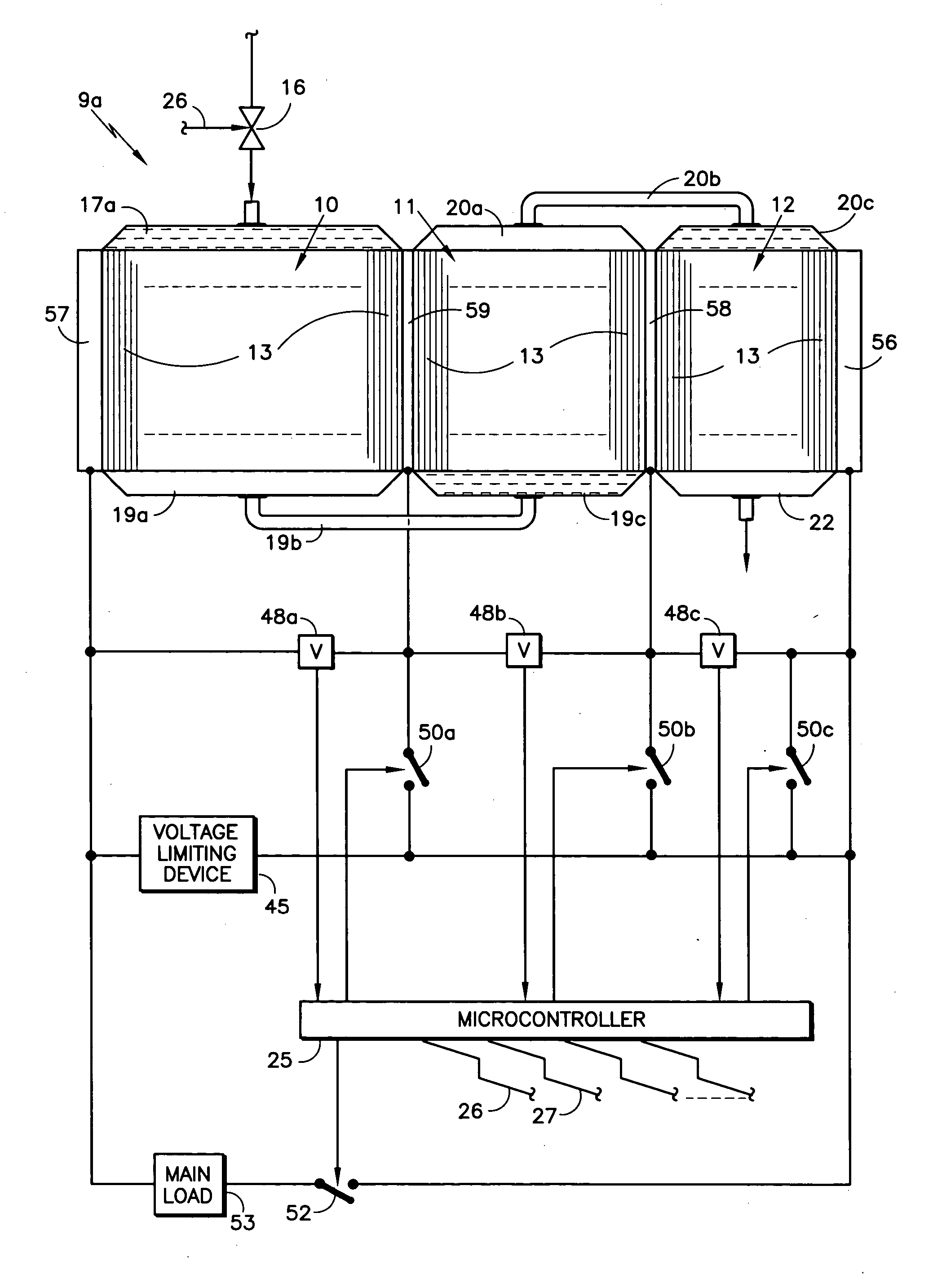
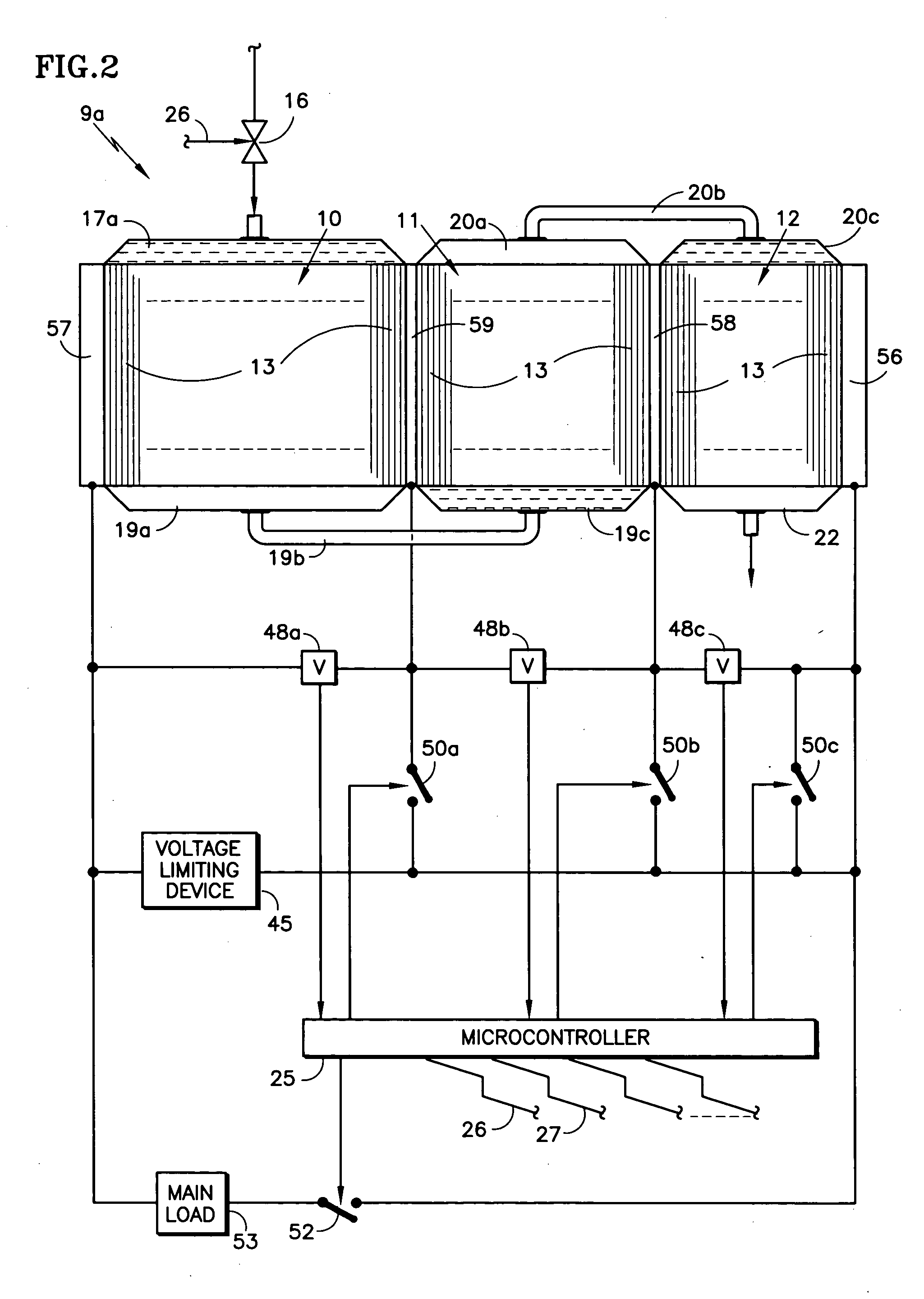
[0021] Referring to FIG. 2, a cascaded fuel cell stack 9a according to the invention includes an inlet fuel distributing fuel inlet manifold 17a at the inlet to the fuel flow fields of the fuel cells 13 in the first group 10. The fuel distributing manifold 17a may be a cascade fuel inlet manifold as described in copending U.S. patent application Ser. No. 10 / 269,654, filed Oct. 10, 2002. The device disclosed therein divides the fuel in half a number of times, such as four times, so that it is evenly distributed across the entire stack of fuel cells, whereby each fuel cell fuel flow field receives a uniform amount of fuel, simultaneously with the fuel flow fields of the other fuel cells. The fuel distributing manifold 17a may also take the form of a permeable baffle inlet fuel gas distributor, as disclosed in copending U.S. patent application Serial No. (Docket No. C-2950), filed Dec. 15, 2003, entitled “Permeable Inlet Fuel Gas Distributor for Fuel Cells”, in which fuel is evenly dis...


PUM


Abstract

A cascaded fuel cell stack (9a) includes a plurality of groups (10-12) of fuel cells (13) connected electrically in series by means of conductive separator plates (58, 59) and current collecting pressure plates (56, 57). Each group has an inlet fuel distributing fuel inlet manifold (17a, 19c, 20c), a fuel exit manifold (19a, 20a) of each group except the last feeding the inlet manifold of each subsequent group. A microcontroller responds to signals from a plurality of voltage sensing devices (48a-48c) to cause corresponding switches (50a-50c) (a) to connect each group, and all preceding groups in the sequence, to a voltage limiting device (VLD) (45), or (b) to connect each group to its own (VLD (45a-45c), in response to sensing a predetermined average cell voltage across the corresponding group. When normal operation occurs, the microcontroller connects the main load and disconnects the voltage limiting device (53) (25).

Description

TECHNICAL FIELD [0001] This invention relates to cascaded control of fuel flow and voltage of cascaded fuel cell stacks, such as during startup and shutdown. BACKGROUND ART [0002] To achieve very high fuel utilizations, about 98% or 99%, when operating a fuel cell stack 9 on pure hydrogen, a cascade fuel flow field, illustrated in FIG. 1, comprises a plurality of groups 10-12 of fuel cells 13 arranged in flow-series relationship so that fuel from a source (not shown) passing through a fuel inlet valve 16 enters a fuel inlet manifold 17, flows through a first group 10 of fuel cells 13, then enters a first turn-around manifold 19, then flows through the second group 11 of fuel cells 13, thence through a second turn-around manifold 20 and through the third group 12 of fuel cells 13, to an exit manifold 22. [0003] For a typical 40 kilowatt fuel cell stack, the first group 10 has a large number of cells 13, which may be on the order of about 200 cells, the second group 11 has a lesser nu...

Claims


Application Information

Patent Timeline
IPC IPC(8): H01M8/04H01M8/24
CPCH01M8/04223H01M8/04559Y02E60/50H01M8/04888H01M8/249H01M8/0488H01M8/04303H01M8/04302H01M8/04225H01M8/04228
Inventor FULLER, THOMAS F.BALLIET, RYAN J.
Owner INT FUEL CELLS
Why Eureka
Try Eureka