
Method and apparatus for automatic data rate control in a wireless communication system

a wireless communication system and data rate control technology, applied in the field of wireless communication systems, can solve the problems of limiting the cost, size and power consumption of wireless devices, limiting the transmission power levels, and limiting the scope of standards, so as to reduce the transmission rate

Inactive Publication Date: 2005-06-30
AGERE SYST INC
View PDF12 Cites 57 Cited by
  • Summary
  • Abstract
  • Description
  • Claims
  • Application Information

AI Technical Summary

Benefits of technology

[0010] According to another aspect of the invention, the data rate controller provides a probation mechanism that allows a higher rate to be evaluated before switching to the higher rate permanently. In addition, the data rate controller can optionally provide a retry balance mechanism that forces a rate fallback when a number of failed transmission exceeds a predefined threshold. The retry balance mechanism monitors a number of frames that required a retry relative to a number of frames that did not require a retry and reduces the transmission rate to a lower rate if a retry balance exceeds a predefined threshold. A disclosed rate fallback feature reduces the transmission rate when a number of failed transmission exceeds a predefined threshold.

Problems solved by technology

The transmit power levels, however, are typically limited by regulations and design constraints of the wireless devices.
In addition, design constraints generally limit the cost, size and power consumption of wireless devices.
The selection of a particular available data rate by a given wireless device, however, is outside the scope of the standards.
As data rates increase, there is a more severe requirement on the tolerable transmit signal error and require more power stage linearity and back off in power level.

Method used


Image

  • Method and apparatus for automatic data rate control in a wireless communication system
  • Method and apparatus for automatic data rate control in a wireless communication system
  • Method and apparatus for automatic data rate control in a wireless communication system

Examples


Embodiment Construction

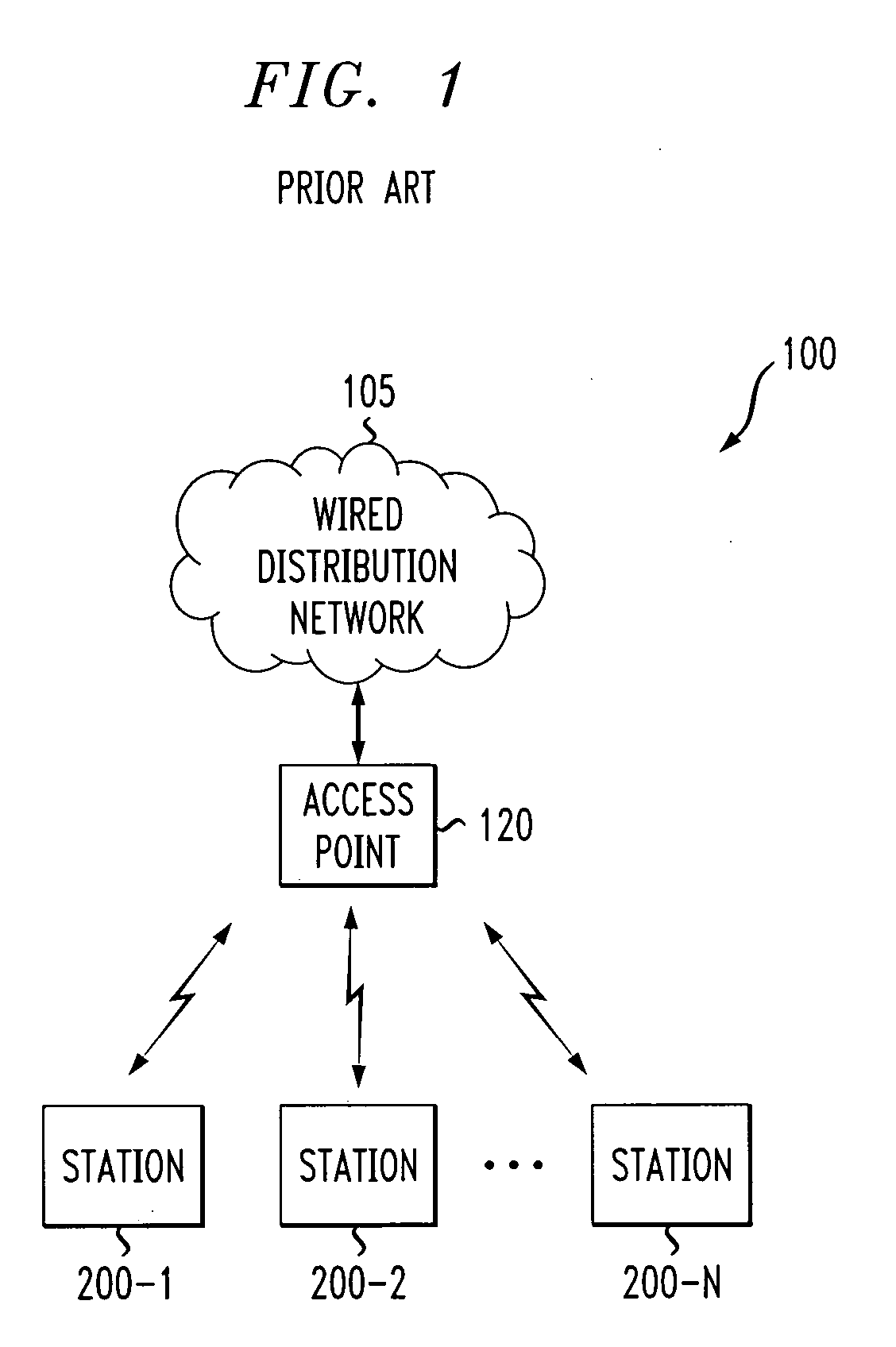
[0019]FIG. 1 illustrates a wireless network environment 100 in which the present invention can operate. The wireless network environment 100 may be, for example, a wireless LAN or a portion thereof. As shown in FIG. 1, a number of stations 200-1 through 200-N, collectively referred to as stations 200 and discussed below in conjunction with FIG. 2, communicate over one or more wireless channels in the wireless digital communication system 100. An access point 120 is typically connected to a wired distribution network 105 with other access points (not shown). The access point 120 typically provides control and management functions, in a known manner. In addition, the access point 120 acts as a central node through which all traffic is relayed so that the stations 200 can rely on the fact that transmissions will originate from the access point 120. The wireless network environment 100 may be implemented, for example, in accordance with the IEEE 802.11 standard or the various extensions...


PUM


Abstract

A method and apparatus are provided for automatic data rate control in wireless communication systems, such as wireless LANs. A data rate controller adapts a transmission rate of said data based on a signal quality and a transmit power level. The data rate controller can also adapt the transmission rate based on one or more of amplifier non-linearities, anticipated signal quality for a next frame transmission, regulatory emission limits and data rate advice. The data rate advice will decrease a data rate if a current signal quality is below a minimum required signal quality for a given data rate and increase a data rate if a current signal quality is above a minimum required signal quality for a given data rate. A probation mechanism allows a higher rate to be evaluated before switching to the higher rate permanently. A retry balance mechanism forces a rate fallback when a number of failed transmission exceeds a predefined threshold. A rate fallback feature reduces the transmission rate when a number of failed transmission exceeds a predefined threshold.

Description

CROSS REFERENCE TO RELATED APPLICATION [0001] The present application is related to U.S. patent application Ser. No. ______, entitled “Method and Apparatus for Automatic Transmit Power Variation in a Wireless Communication System,” filed contemporaneously herewith and incorporated by reference herein.FIELD OF THE INVENTION [0002] The present invention relates generally to wireless communication systems, such as wireless local area networks (LANs), and more particularly, to data rate control techniques in such wireless communication systems. BACKGROUND OF THE INVENTION [0003] Wireless communications can generally be made more reliable by increasing the power level of the transmitter or by decreasing the transmission data rate to a more robust data rate. The transmit power levels, however, are typically limited by regulations and design constraints of the wireless devices. For example, most countries or regions have regulations that specify particular power level limits for each frequ...

Claims


Application Information

Patent Timeline
IPC IPC(8): H04B7/005H04L1/00H04L1/16H04L12/28
CPCH04L1/0002H04L1/0017H04L1/16H04W28/04H04W84/12H04W52/226H04W52/26H04W52/48H04W28/22
Inventor HIDDINK, GERRIT WILLEMHOMSMA, ALFRED JACOBKAMERMAN, ADRIAANMONTEBAN, LEO
Owner AGERE SYST INC
Learn More