System for fixing a part to a bone element

a technology for fixing parts and bone elements, applied in the field of systems for fixing parts to bone elements, can solve the problems that the connection between parts and bone elements cannot be obtained through natural bone growth, and the last solution is not practical, and achieves the effect of simple removal, easy production and implanting

Active Publication Date: 2005-06-30
NORGINE VENTURES BV +1
View PDF8 Cites 62 Cited by
  • Summary
  • Abstract
  • Description
  • Claims
  • Application Information

AI Technical Summary

Benefits of technology

[0026] Advantageously, the system according to the invention is simple and easy to produce and to implant. It does not necessitate any

Problems solved by technology

It sometimes happens, however, that the location of this part relative to the bone element on which it is to be fixed does not permit the use of screws or the like, because there is insufficient clearance in front of the part relative to the bone element to be able to pre-position the screws before screwing them into the bone element by passing them first through slots or the like made in said part.
However, in this case the connection between the part and the bone element can

Method used


Image

  • System for fixing a part to a bone element
  • System for fixing a part to a bone element
  • System for fixing a part to a bone element

Examples


Embodiment Construction

)

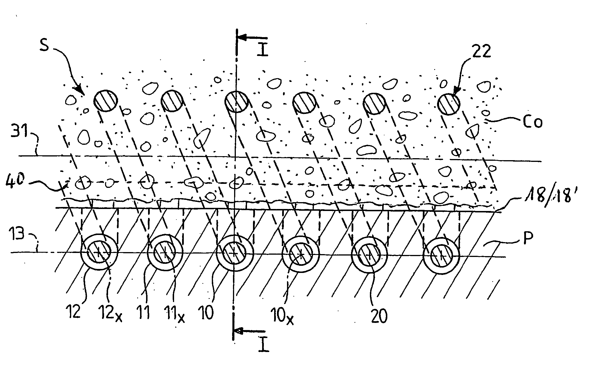
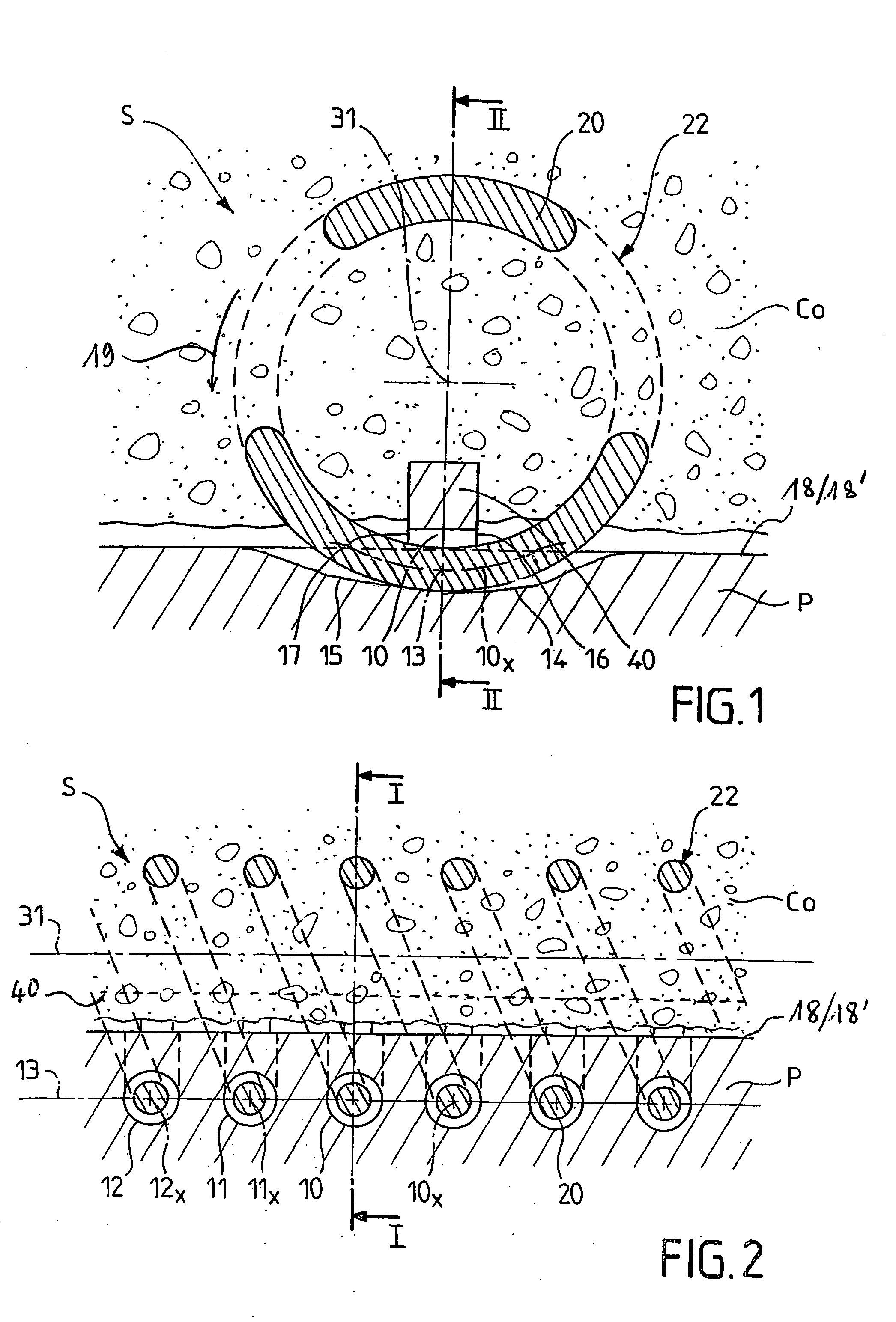
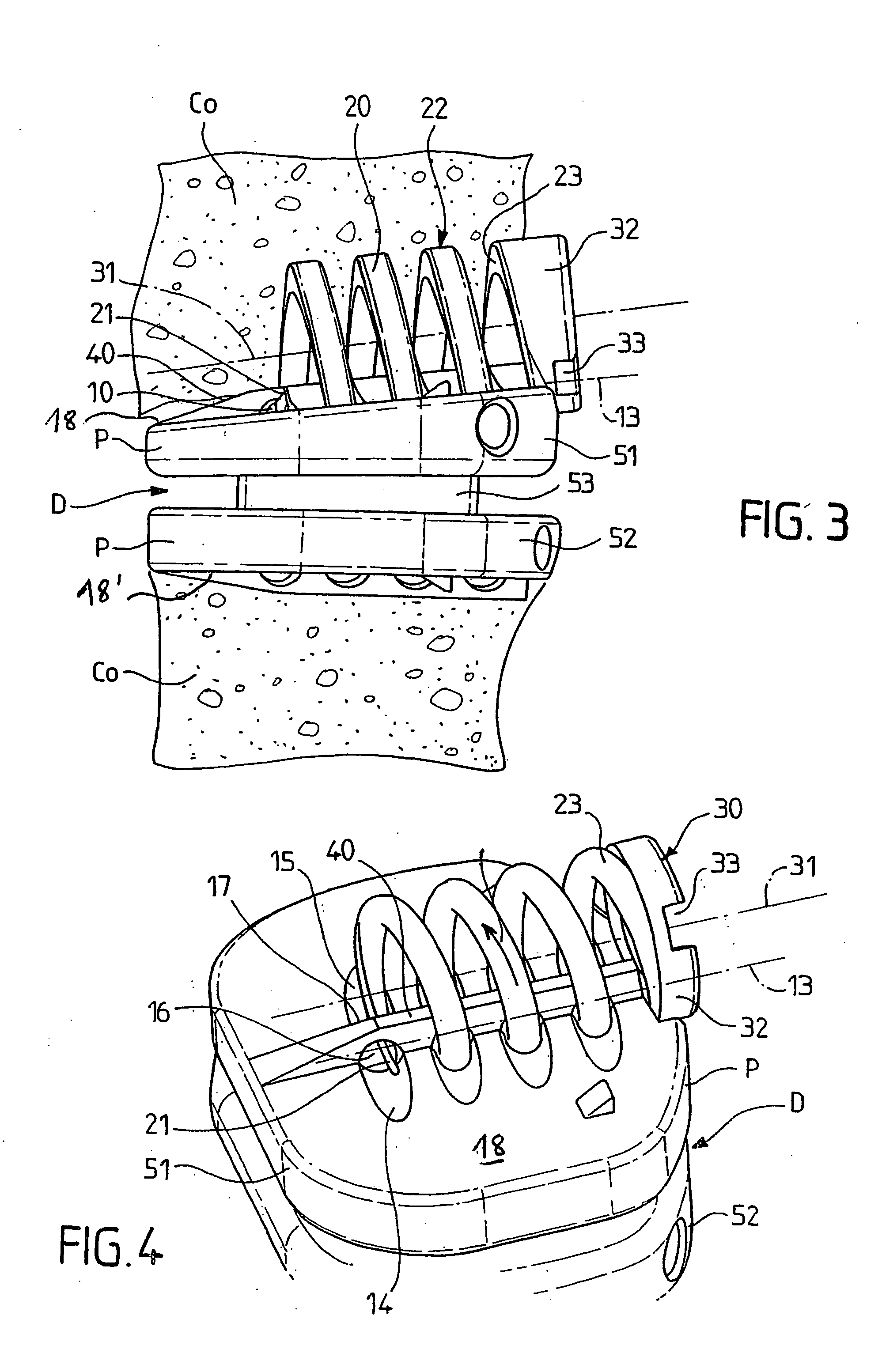
[0032] The present invention concerns system S for fixing a part P to a bone element Co.

[0033] The part P comprises at least one through-hole 10 formed, for example, on an outer surface 18, 18′, this through-hole having an axial line 10x.

[0034] The system S is a rigid rod 20 comprising a first end 21 configured to penetrate into the element Co, the rod being wound into a spiral 22 substantially along a first helicoidal curve.

[0035] The system additionally comprises means 30 for driving the rod 20 in rotation about the axis 31 of the first helicoidal curve in such a way that the first end 21 of the rod 20 moves alternately into the element Co and out of the element, and that, in its movement of rotation outside the element Co, the first end 21 of the rod 20, which for example is pointed or beveled, moves at least once into the through-hole 10.

[0036] It will be noted that the cross section of the through-hole 10 can be circular and have a cross section slightly greater than the m...


PUM


Abstract

The invention relates to a system which is used to fix a part to a bone element. The invention is essentially characterized in that it consists of: at least one hole which is disposed in part; a rigid rod comprising a first end, the rod being wound into a spiral along a first helicoidal curve; and a device for rotating the rod around the axis of the first helicoidal curve, such that the first end of the rod moves alternatively inside and outside the bone element and, during the rotation thereof, the first end of the rod moves at least once into the opening. The invention is particularly suitable for fixing intervertebral disks or fusion cages to the vertebral bodies of two consecutive vertebrae.

Description

BACKGROUND OF THE INVENTION [0001] (1). Field of the Invention [0002] The present invention concerns systems for fixing a part to a bone element, with a particularly advantageous application in the spinal sector, for example for fixing an interbody cage or an intervertebral disk to the vertebral bodies of two consecutive vertebrae. [0003] (2). Prior Art [0004] Intervertebral prostheses which are implanted between the two vertebral bodies of two vertebrae are already known. These prostheses comprise, for example, plates which have to be fixed, respectively, to the two vertebral bodies. [0005] When fixing a part, for example a metal part, to a bone element, and when wanting this part to be immediately integral with this bone element, screws or the like are generally used. It sometimes happens, however, that the location of this part relative to the bone element on which it is to be fixed does not permit the use of screws or the like, because there is insufficient clearance in front of...

Claims


Application Information

Patent Timeline
IPC IPC(8): A61B17/86A61F2/00A61F2/30A61F2/44A61F2/46
CPCA61B17/86A61F2310/00023A61F2/4455A61F2/446A61F2/4611A61F2002/30153A61F2002/30154A61F2002/30158A61F2002/30289A61F2002/30649A61F2002/3082A61F2002/30879A61F2002/4475A61F2230/0019A61F2230/0021A61F2230/0026A61F2230/0091A61F2/4425A61F2002/30593
Inventor PETIT, DOMINIQUE
Owner NORGINE VENTURES BV
Why Eureka
Try Eureka