Cleaning tool and method for manufacturing cleaning portion constituting the cleaning tool

a technology of cleaning tool and cleaning portion, which is applied in the field of cleaning tools, can solve the problems of not removing dust, offering satisfactory wiping performance, and the conventional duster has no wiping function, so as to achieve excellent wiping performance, easy cleaning of tight spaces, and easy catching of dus

Inactive Publication Date: 2005-07-07
YAMADA CHIYOE
View PDF40 Cites 19 Cited by
  • Summary
  • Abstract
  • Description
  • Claims
  • Application Information

AI Technical Summary

Benefits of technology

[0014] Since the pleated component is formed on the cleaning surface with the present invention, the pleated component can get into tight spaces and irregular surfaces, allowing dust to be trapped and wiped away more effectively, and allowing tight spaces to be cleaned more easily.
[0015] With the present invention, a pleated component is formed by making cuts in a sheet bundle comprising a plurality of stacked sheets, and the sheet bundle is bent so that the pleated components overlap with one another (first bending step), and after this first bending, second bending is performed so that the pleated components again overlap with each other, thereby bending the bulging component in a U-shape, so there are many pleats per unit of surface area, allowing the pleated component as a whole to be more voluminous, the result of which is that wiping performance is excellent.
[0016] Because there is a bulging component with the present invention, the handle insertion component can be formed in this bulging component, and as a result there is no need to stick together separate sheets in order to form the handle insertion component. Also, when a sheet bundle cut surface is formed at the upper part of the bulging component so as to form a nappy surface, or when the pleated component is formed in the bulging component itself, the bulging component can be constituted as the cleaning surface, and as a result two surfaces (the pleated component underneath the bulging component and the top surface of the bulging component) function as cleaning surfaces, which improves cleaning efficiency and makes the tool more convenient to use.
[0017] An advantage to the method of the present invention for manufacturing a cleaning component is that a cleaning component with good wiping performance can be manufactured easily, with a simple procedure.

Problems solved by technology

Therefore, a conventional duster has no wiping function, and so can not remove dust without scattering it into the air.
With this cleaning tool, however, the wiping component did not offer satisfactory wiping performance, and the tool was also inconvenient to use.
However, this hand wiper did not offer satisfactory wiping performance, either, and furthermore it was incapable of cleaning well in confined spaces.

Method used


Image

  • Cleaning tool and method for manufacturing cleaning portion constituting the cleaning tool
  • Cleaning tool and method for manufacturing cleaning portion constituting the cleaning tool
  • Cleaning tool and method for manufacturing cleaning portion constituting the cleaning tool

Examples


first embodiment

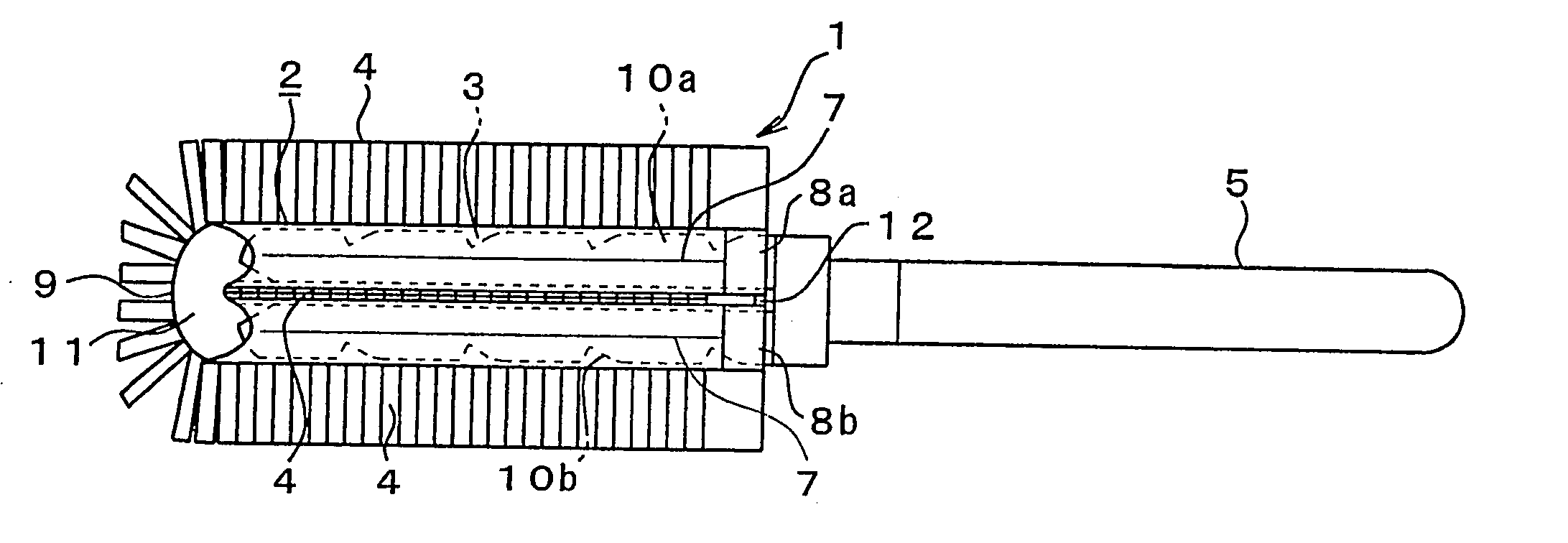
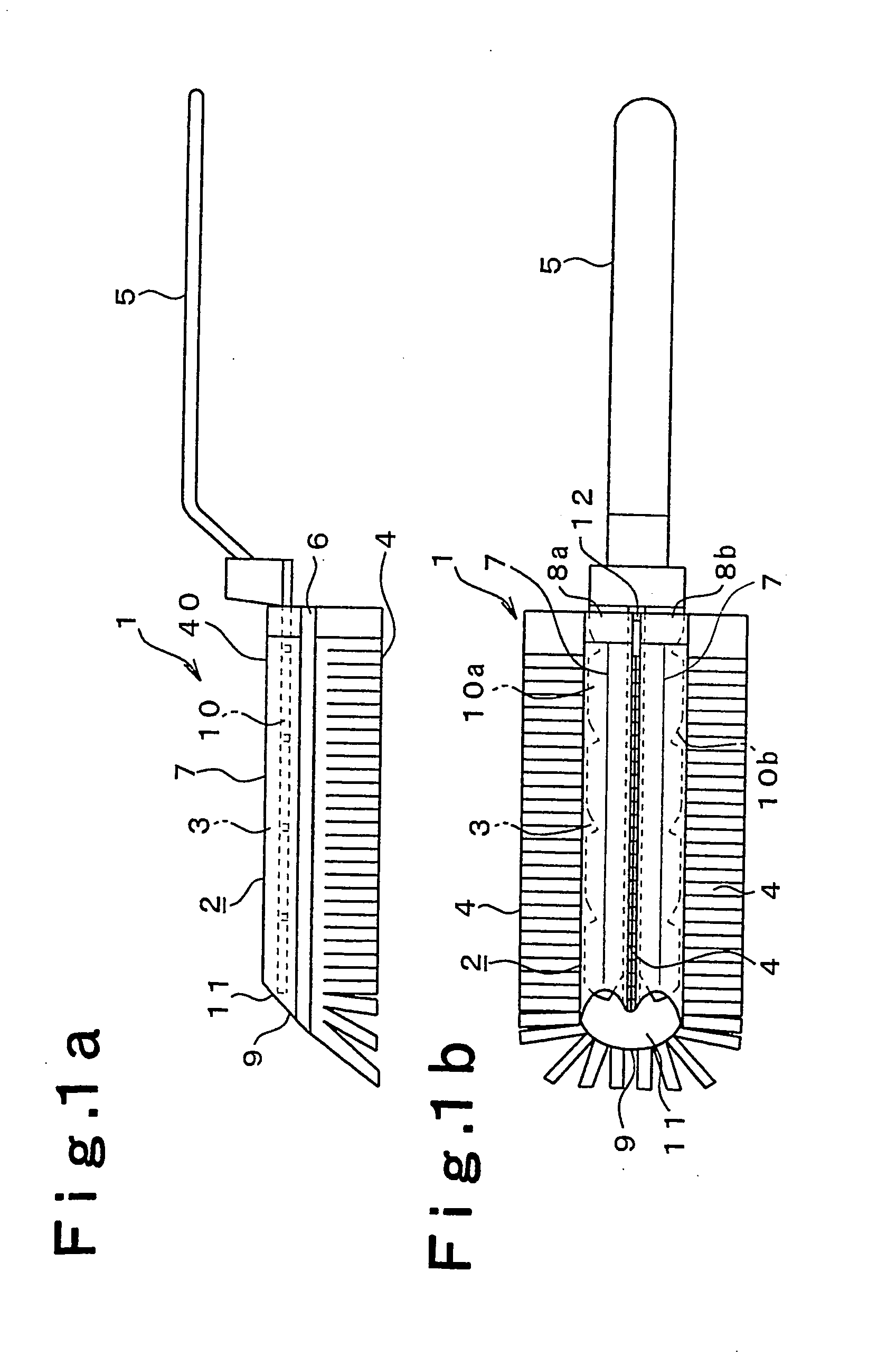
[0032]FIG. 1 shows the present invention. A cleaning tool 1 comprises a cleaning component 2 and a handle component 5, and the cleaning component 2 comprises a bulging component 40 bent in a U-shape, a handle insertion component 3 formed inside the bulging component 40, and a pleated component 4 formed along and underneath the bulging component 40. The cleaning component 2 is constituted such that a sheet bundle comprising a plurality of stacked sheets is bent twice as discussed below (in FIG. 1, 7 is the first bent component and 9 is the second bent component). A linear seal component 6 is provided, parallel to the bent component 7, to the sheet bundle that has been bent from the bent component 7. The space formed by the provision of this seal component 6 constitutes the handle insertion component 3. The seal component 6 is formed by heat fusion, for example. 8a and 8b are insertion openings in the handle insertion component 3.

[0033] Providing the first seal component 6 parallel to...

second embodiment

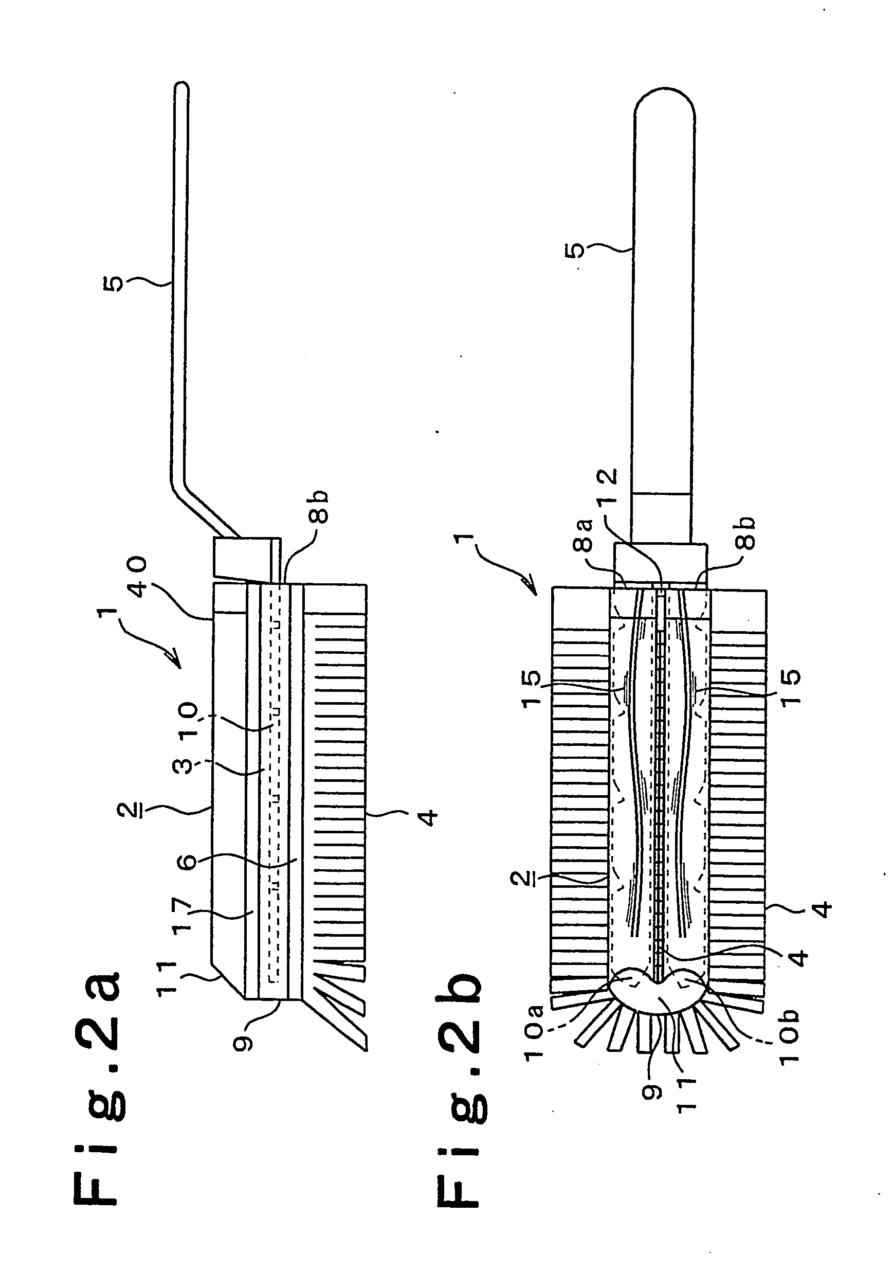
[0045]FIG. 2 illustrates the present invention. In this embodiment, a sheet bundle cut surface 15 is formed on the upper part of the bulging component 40, which forms a raised nap on the upper part of the bulging component 40. To form this raised nap on the upper part of the bulging component, cut lines should be made along the bend line in the first bending step of the sheet bundle. A nappy surface is formed in the course of this sheet cutting.

[0046] Also, in this embodiment two seal components, a first seal component 6 and a second seal component 17, are provided as the seal component, and the space formed by these two seal components constitutes the handle insertion component 3.

third embodiment

[0047]FIG. 3 illustrates the present invention. In this embodiment, a pleated component 16 is provided to the bulging component 40 itself. The pleated component 16 is provided to the upper part of the bulging component 40, and has the same narrow rectangular shape as the pleated component 4 under the bulging component 40.

[0048] To form this pleated component 16 on the upper part of the bulging component 40, a cut line is made along the bend line in the first bending step of the sheet bundle, and numerous cuts are made along the cut end faces of this cut line.

[0049] Again in this embodiment, two seal components, a first seal component 6 and a second seal component 17, are provided as the seal component, and the space formed by these two seal components constitutes the handle insertion component 3.

[0050] Next, an example of the method for manufacturing the cleaning component 2 will be described through reference to FIGS. 4 to 6.

[0051] First, a sheet is manufactured by piling up sho...


PUM

PropertyMeasurementUnit
widthaaaaaaaaaa
widthaaaaaaaaaa
widthaaaaaaaaaa

Abstract

The present invention is a cleaning tool used to clean furniture, electrical products, interior walls, and so forth. It is an object of the present invention to provide a cleaning tool that traps dust very well and is excellent at removing dirt.
The cleaning tool of the present invention comprises a cleaning component (2) and a handle component (5), with the cleaning component (2) being removably attached to the handle component (5). The cleaning component (2) comprises a bulging component (40) bent in a U-shape, a handle insertion component (3) formed inside said bulging component (40), and a pleated component (4) formed along and underneath the bulging component (40). A support component (10) of the handle component (5) is inserted in the handle insertion component (3) of the bulging component (40), and the cleaning component (2) is supported at the distal end of the handle component (5).

Description

TECHNICAL FIELD [0001] This invention relates to a cleaning tool used for wiping, and to a method for manufacturing a cleaning component that constitutes part of a cleaning tool. BACKGROUND ART [0002] A duster has been used in the past as a cleaning tool for dusting chests and other such furniture, computers, lighting, and other such electrical products, and the interior walls, thresholds, molding, and so forth of buildings. [0003] A duster has a structure in which a plurality of cord-like strips are attached to the distal end of a handle component, and dust is removed by brushing a dusty surface with these cord-like strips. Therefore, a conventional duster has no wiping function, and so can not remove dust without scattering it into the air. [0004] In an attempt to ameliorate this drawback to dusters, a cleaning tool in which a cleaning cloth equipped with a wiping component and a dusting component is provided to a head at the distal end of a handle component has been proposed in J...

Claims


Application Information

Patent Timeline
Patent Type & Authority Applications(United States)
IPC IPC(8): A46B7/04A47L13/20A47L13/38
CPCA46B7/04A47L13/38A47L13/20A46B2200/3026
Inventor YAMADA, KIKUO
Owner YAMADA CHIYOE
Why Eureka
Try Eureka