Attitude sensing device

a technology of attitude and sensing device, which is applied in the direction of surveying, navigation, instruments, etc., can solve the problems of difficult to predict the settlement of the package, the complexity and size of the sensor package is significantly increased by the gimbal, and the general knowledge of the three-dimensional space of each packag

Inactive Publication Date: 2005-07-07
QINETIQ LTD
View PDF11 Cites 36 Cited by
  • Summary
  • Abstract
  • Description
  • Claims
  • Application Information

AI Technical Summary

Benefits of technology

[0010] Viewed from a first aspect, the present invention provides an attitude sensing device for determining the attitude of a reference axis of a package with which the attitude sensing device is associated, the attitude sensing device comprising a first electromechanical sensor having a rotatable shaft operable to rotate about its axis to any shaft angle, the first electromechanical sensor comprising a device the impedance value of which varies in dependence upon the shaft angle except for an interval of the shaft angle over which the impedance value remains substantially constant, and being operable to provide a first electrical signal in dependence on the shaft angle, the attitude of the reference axis being derivable from the first electrical signal; and a mass coupled to the shaft, the mass causing the shaft to rotate as the mass adopts a gravity-induced position, characterised in that the device further comprises a second such electromechanical sensor axially aligned with the first and arranged such that respective

Problems solved by technology

In typical deployment conditions, this can be difficult.
For example, when such an array is deployed onto a seabed, it is difficult to predict how the packages will settle on to the seabed, and so the orientation of each package in three-dimensional space is not in general known.
Further, in settling on the seabed, the package may pitch or roll any number of t

Method used


Image

  • Attitude sensing device
  • Attitude sensing device
  • Attitude sensing device

Examples


Embodiment Construction

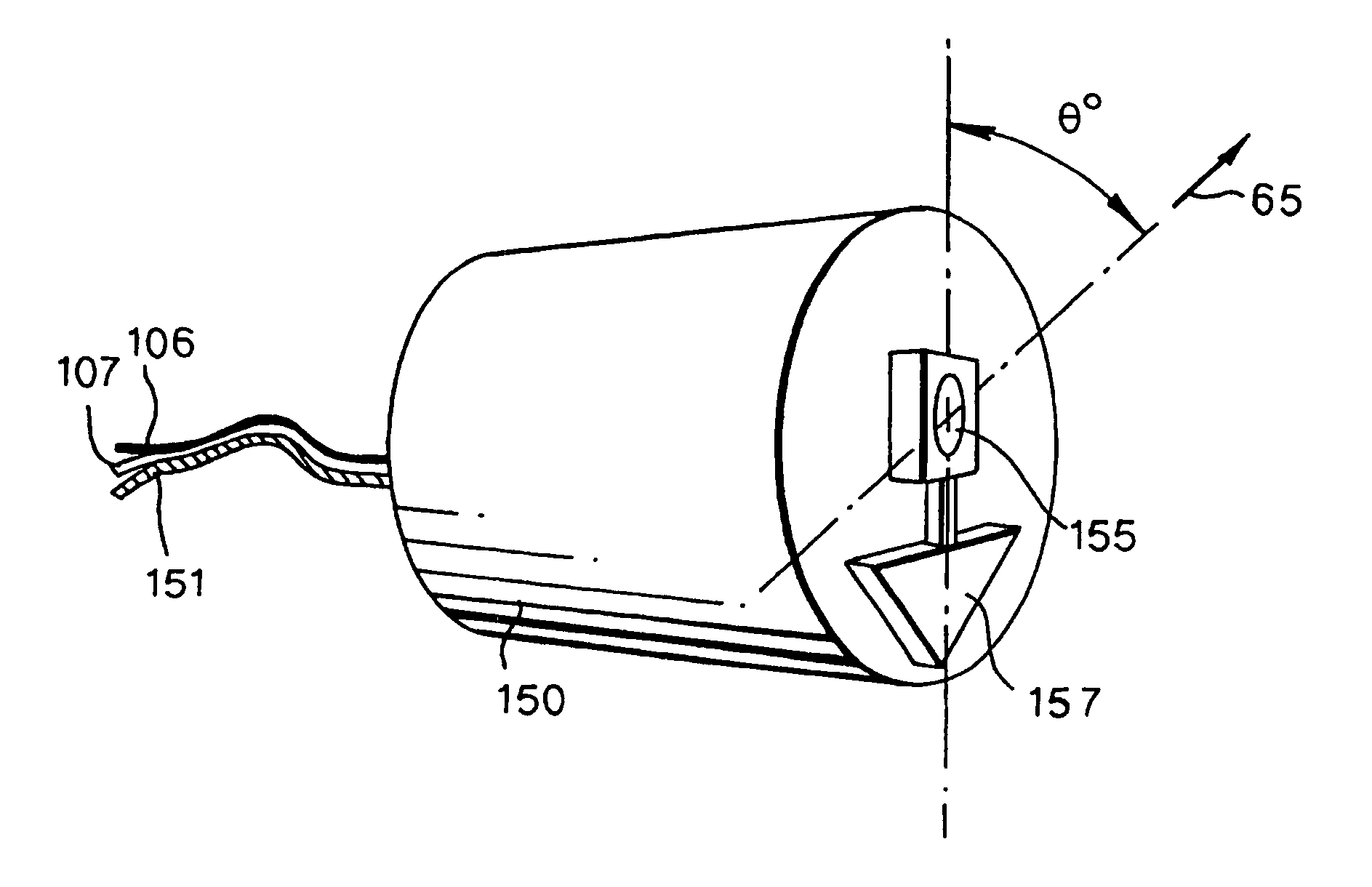
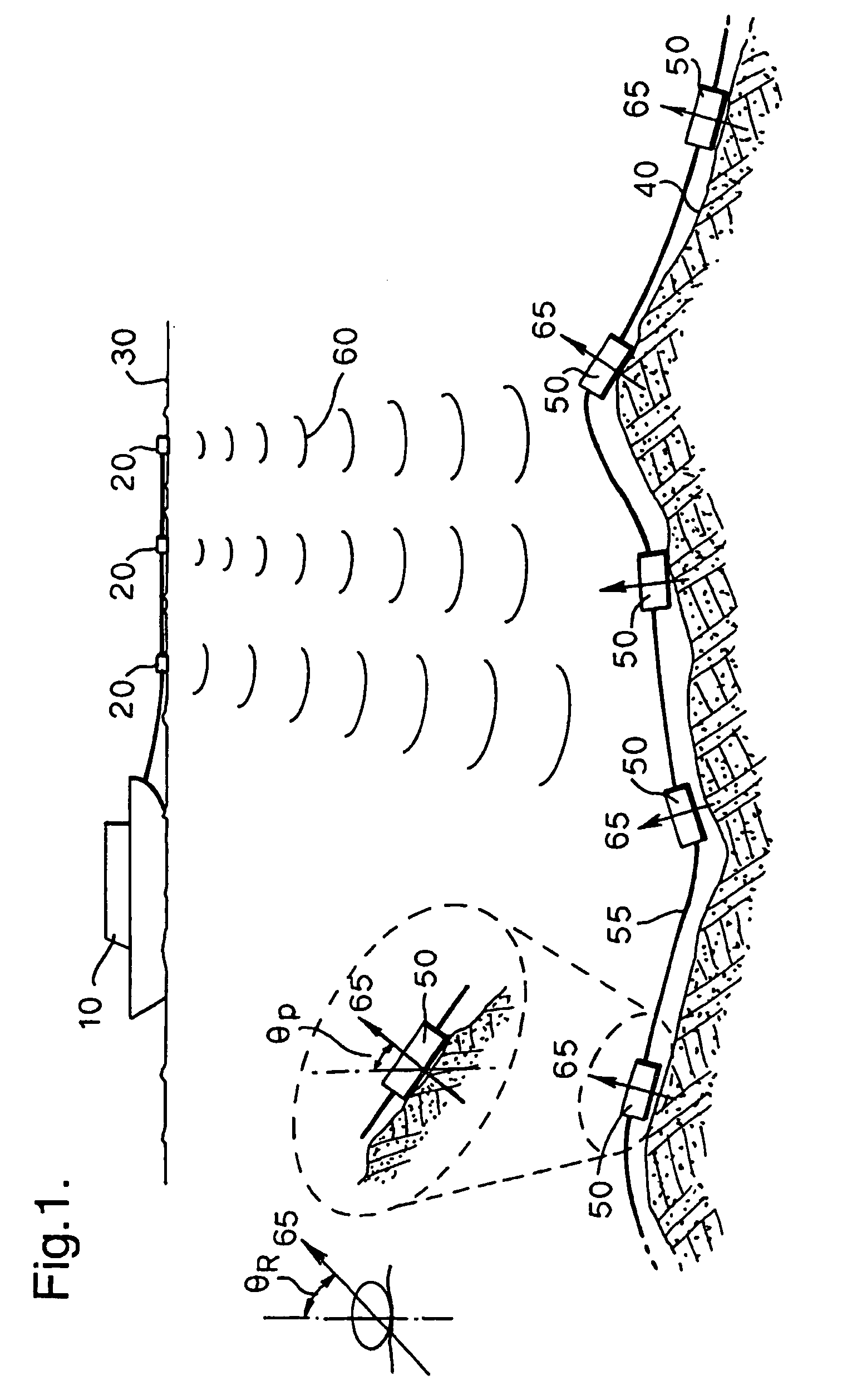
[0043]FIG. 1 is a diagram illustrating a deployment of a seabed seismic array.

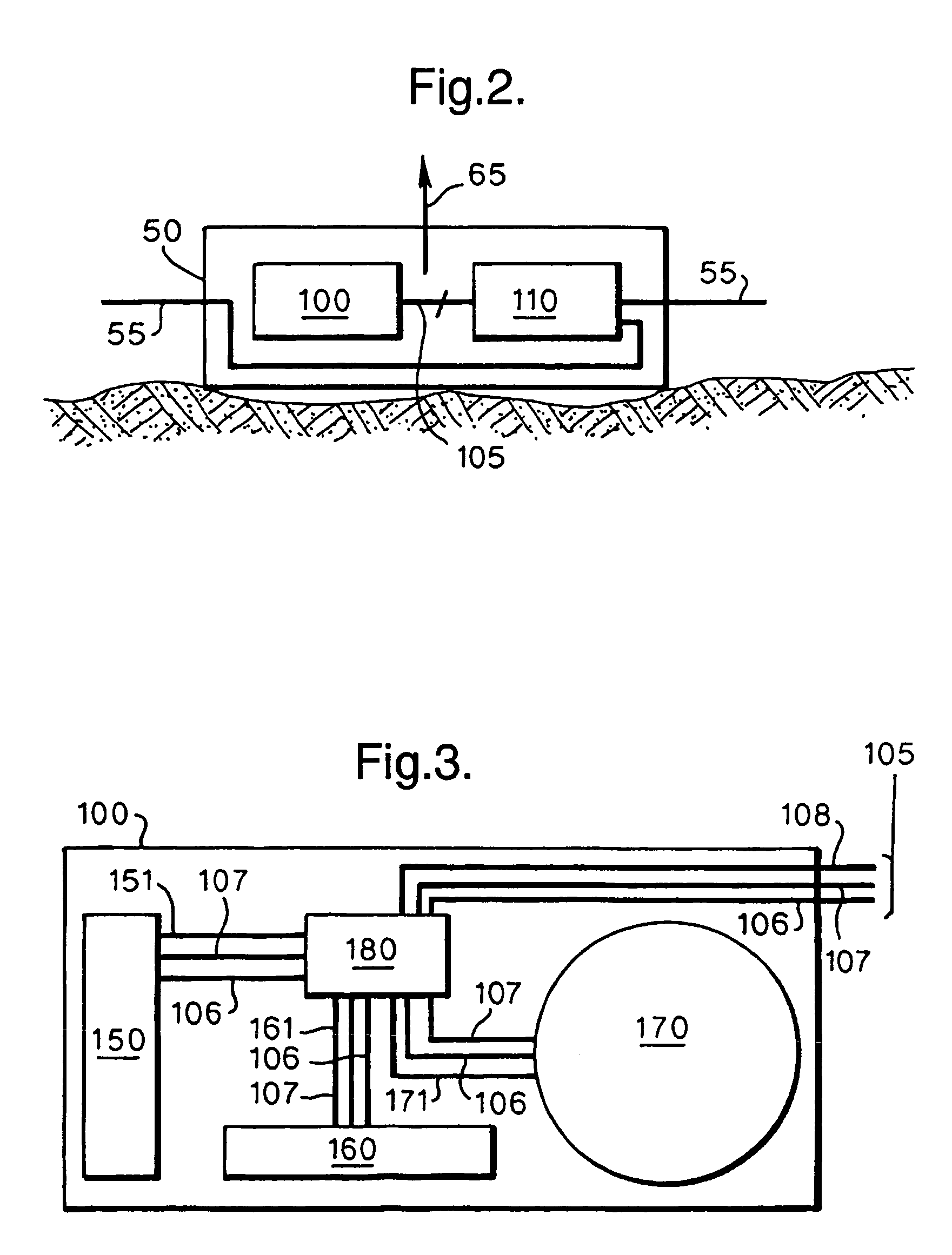
[0044] The array consists of a plurality of packages 50 coupled by a fibre optic cable 55. Each package 50 contains fibre optic sensors which are becoming a well-established technology for a range of applications such as, for example, geophysical applications. Fibre optic sensors can take a variety of forms. For example, fibre optic sensors may be arranged to act as static pressure sensors or static temperature sensors. Additionally, fibre optic sensors have also been developed for measuring dynamic quantities such as acoustic and seismic signals, examples of such dynamic fibre optic sensors being fibre optic hydrophones and fibre optic geophones. A hydrophone is a device for the measurement of dynamic pressure in a fluid, whilst a geophone is a device for the measurement of vibration (in practice, this can either be an accelerometer or a displacement sensor). As mentioned previously, the selection and ar...


PUM


Abstract

The present invention provides an attitude sensing device and an attitude sensing method, and in particular techniques for determining an attitude in three-dimensional space of a reference axis of a package with which the attitude sensing device is associated. The attitude sensing device comprises an electromechanical sensor having a rotatable shaft operable to rotate about its axis to any shaft angle and a mass coupled to the shaft. The mass causes the shaft to rotate as the mass adopts a gravity-induced position. The electromechanical sensor is operable to provide an electrical signal in dependence on the shaft angle. The attitude of the reference axis being derivable from the electrical signal. By this approach, a simple arrangement is provided by which the attitude of the reference axis may easily be determined over the required operating range.

Description

FIELD OF THE INVENTION [0001] The present invention relates to an attitude sensing device and an attitude sensing method, and in particular to techniques for determining an attitude in three-dimensional space of a reference axis of a package with which the attitude sensing device is associated. DESCRIPTION OF THE PRIOR ART [0002] In many technological fields it is often necessary to determine the attitude or orientation of an apparatus. There are many reasons for needing to determine the attitude of an apparatus, for example, the operating characteristics of the apparatus may vary depending on its attitude. Also or alternatively, the device may be required to perform varied functions in dependence on its attitude. Additionally, the device may be utilised to collect data and the characteristic of that data may vary dependent on the attitude of the device. Hence, attitude sensing devices are often utilised to provide information relating to the attitude of an apparatus. [0003] In one ...

Claims


Application Information

Patent Timeline
IPC IPC(8): G01C9/06G01C9/12G01V1/16
CPCG01C9/06G01V1/16G01C2009/068G01C9/12
Inventor TANNER, MARK ANDREW
Owner QINETIQ LTD
Why Eureka
Try Eureka