
Electronic Stitch Length Regulator for Home Sewing Machines

a technology of electronic stitch length and sewing machine, which is applied in the direction of programmed sewing machine, mattress sewing, textiles and papermaking, etc., can solve the problems of uneven stitching, short stitch length, and long stitch length

Inactive Publication Date: 2005-07-07
HOOKE DAVID ANDREW
View PDF17 Cites 20 Cited by
  • Summary
  • Abstract
  • Description
  • Claims
  • Application Information

AI Technical Summary

Benefits of technology

[0002] The present invention, in one embodiment thereof, comprises a sensor to measure translational speed of a sewing machine carriage electrically connected to electronic circuitry which takes the signal generated by the sensor as input and outputs an electrical resistance value in Ohms. This electrical resistance, when applied to the foot pedal control electrical connector of the sewing machine, sets the sewing machine rotational speed. As the sensor detects varying translational speed, the output resistance varies in concert which, in turn, varies the sewing machine rotational speed. In the present embodiment of the invention, the sensor is mounted on the end of a rod, which pivots in a base plate placed on top of a carriage and under the sewing machine. The sensor outputs two signals. The first signal is an alternating voltage with a frequency proportional to the rate of position change, or speed, of the longitudinal axis. The second sig

Problems solved by technology

However, free motion quilting, as it is called in the art, does not use the sewing machine feed dogs to move the fabric through the sewing machine.
The result is uneven stitching.
For instance if the needle is moving up and down quickly, but the fabric is moving slowly, the result is a very short stitch length.
Conversely, if the needle is moving slowly and the fabric is moving quickly, the result is a very long stitch length.
This is a difficult if not impossible procedure to master.

Method used


Image

  • Electronic Stitch Length Regulator for Home Sewing Machines
  • Electronic Stitch Length Regulator for Home Sewing Machines
  • Electronic Stitch Length Regulator for Home Sewing Machines

Examples


Embodiment Construction

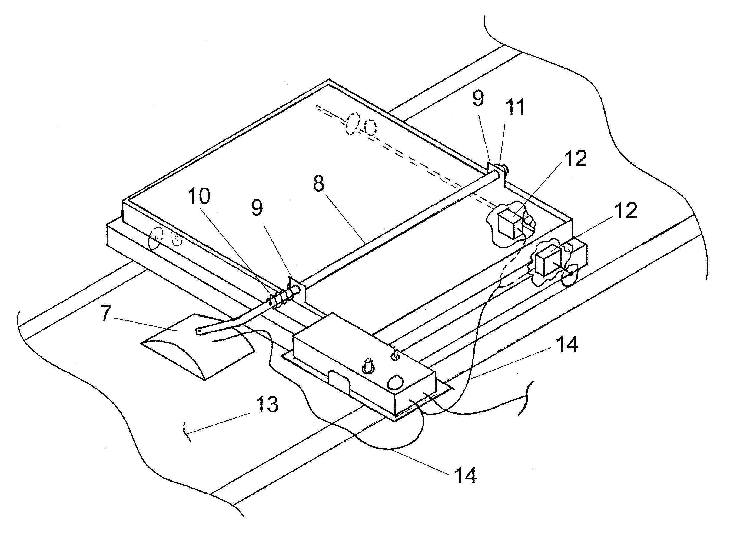
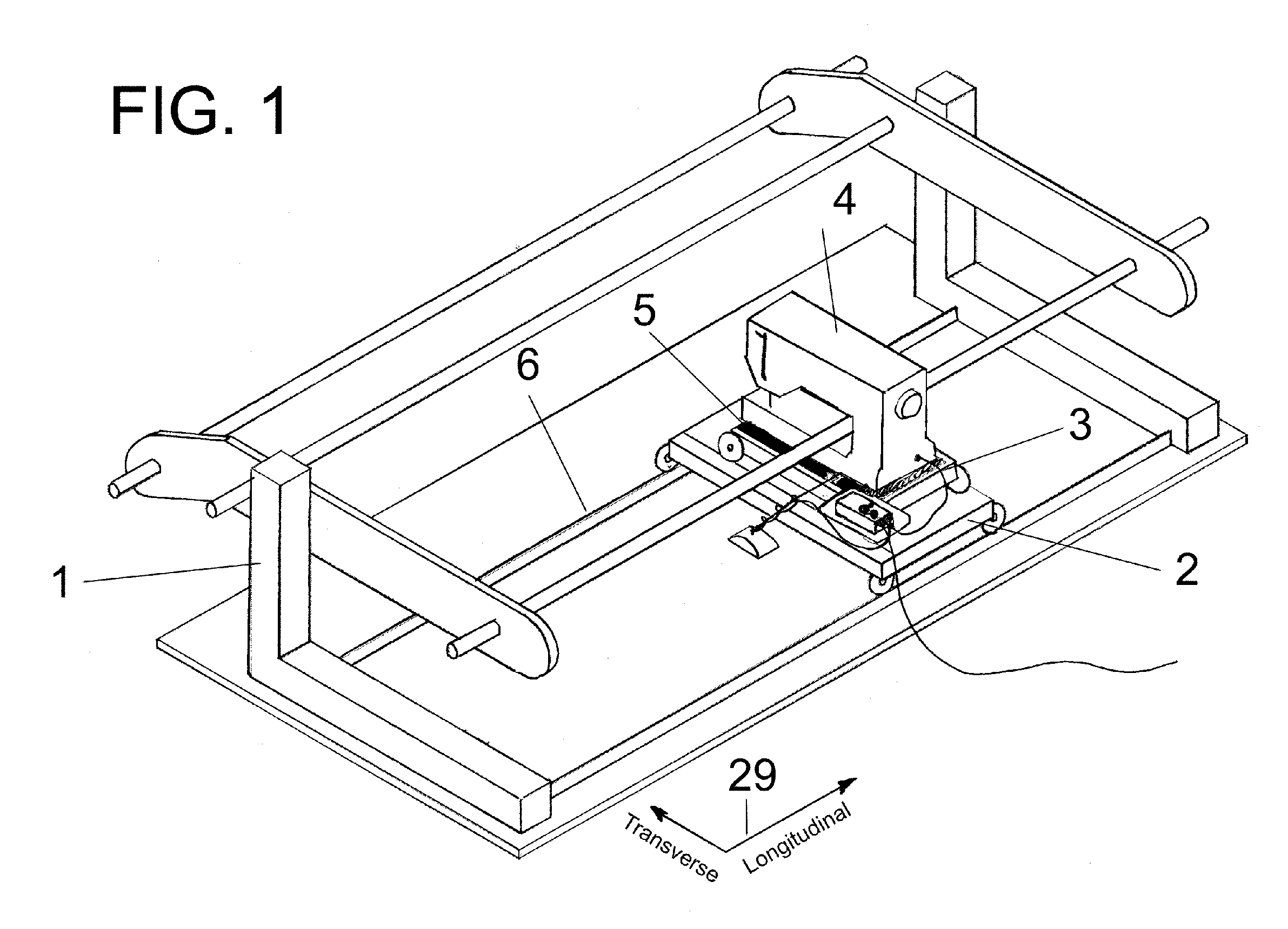
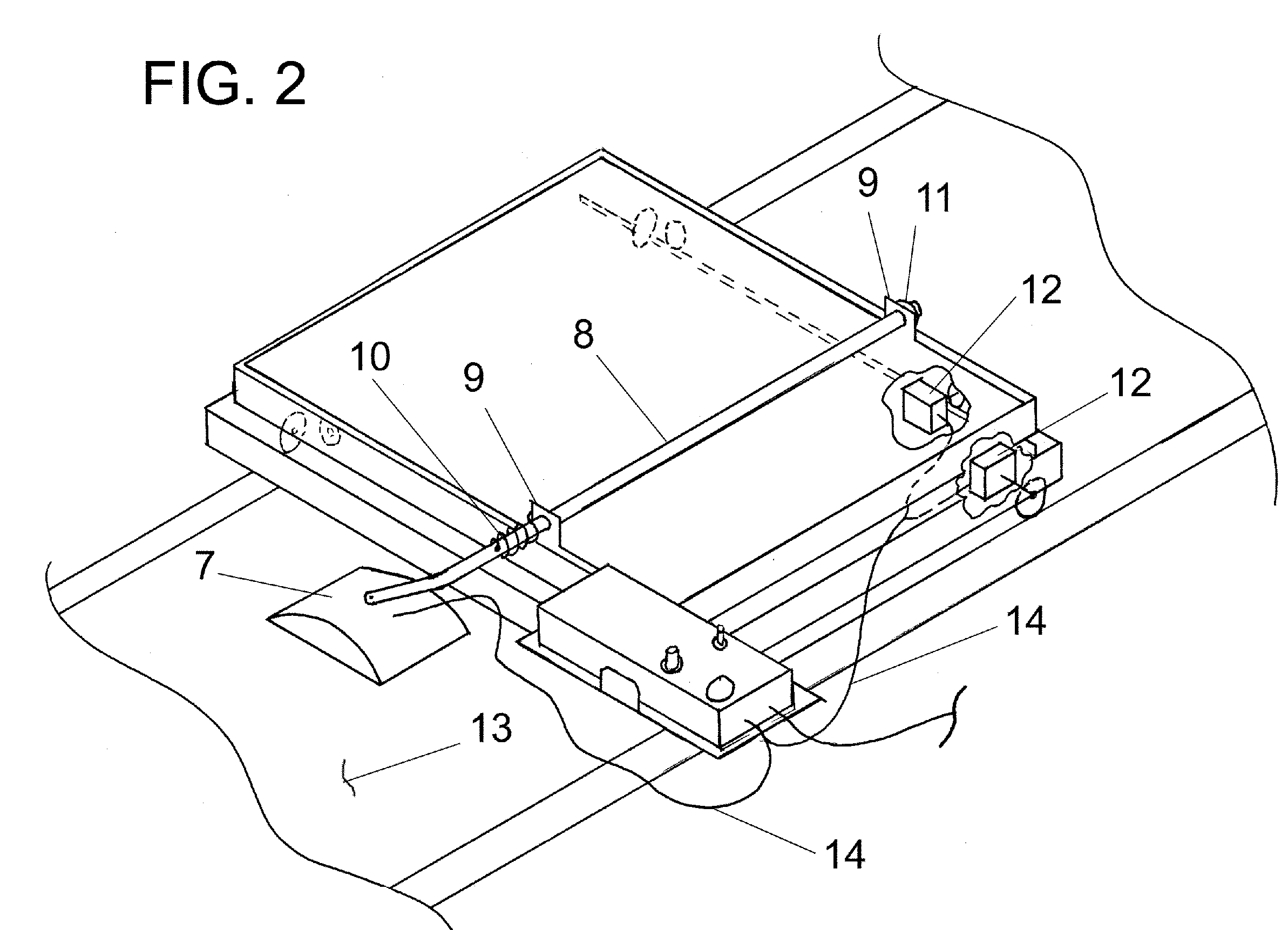
[0008]FIG. 1 illustrates a quilting frame 1 and its components used for reference in this patent. The frame 1 is described in detail in U.S. Pat. No. 6,615,756. The components of frame 1 of interest in this invention are the longitudinal carriage 2 and the transverse carriage 3 with reference to the coordinate system 29. The sewing machine 4 is placed on top of the base plate 5 which is placed on the transverse carriage 3 which is placed on top of the longitudinal carriage 2 which rides on rails 6. The transverse carriage 3 has guide wheels suitably fixed such that only movement in the transverse direction is possible. Similarly, the longitudinal carriage 2 has guide wheels suitably fixed to it such that only longitudinal movement is possible. The sewing machine 4 can move in both the transverse and longitudinal directions using this arrangement. FIG. 2 illustrates the mounting of the position sensor 7 to the sensor arm 8 in one embodiment. The sensor 7 is pivotally mounted to the s...


PUM


Abstract

This invention comprises a means to control stitch length of household sewing machines when used on free-motion quilting frames. A sensor in the form of a computer mouse or a pair of sensors in the form of optical encoders is used to determine the translational speed of the set of carriages that hold the sewing machine. This information is sent to electronic circuitry that converts this information to an electrical resistance which is applied to the foot pedal control electrical connector on the sewing machine. When thusly applied, this resistance sets the rotational speed of the sewing machine. This invention achieves stitch length uniformity by maintaining the proper relationship between the input signal from the sensor or sensors caused by carriage translation and the output resistance to the sewing machine which controls its rotational speed.

Description

BACKGROUND OF INVENTION [0001] Typically machine quilting is performed by using a sewing machine which uses a mechanical means to control stitch length. Consistent stitch length is accomplished by a set of feed dogs located under the throat plate of the sewing machine that are in contact with the fabric being sewn which, in turn, is in contact with the presser foot of the sewing machine. As the machine runs, the feed dogs alternately grab and release the fabric in precise timing with the up and down motion of the needle. The result is an even stitch based on a mechanical means. However, free motion quilting, as it is called in the art, does not use the sewing machine feed dogs to move the fabric through the sewing machine. In free motion quilting, the quilter controls the rate at which the fabric is moved through the machine independently from the up and down rate of the needle. The result is uneven stitching. For instance if the needle is moving up and down quickly, but the fabric ...

Claims


Application Information

Patent Timeline
IPC IPC(8): D05B11/00D05B19/00D05B27/22D05B69/18
CPCD05B69/18D05B11/00
Inventor HOOKE, DAVID ANDREW
Owner HOOKE DAVID ANDREW
Features
  • Generate Ideas
  • Intellectual Property
  • Life Sciences
  • Materials
  • Tech Scout
  • Unparalleled Data Quality
  • Higher Quality Content
  • 60% Fewer Hallucinations
Learn More