Mooring apparatus

a floating vessel and mooring technology, applied in passenger handling apparatus, special-purpose vessels, transportation and packaging, etc., can solve the problems of transferring lng between two offshore structures, affecting the safety of passengers, and posing a number of significant technical difficulties, so as to increase the buoyancy of the dock and suppress the effect of differential motion

Active Publication Date: 2005-07-07
BLUEWATER ENERGY SERVECES BV
View PDF2 Cites 30 Cited by
  • Summary
  • Abstract
  • Description
  • Claims
  • Application Information

AI Technical Summary

Benefits of technology

[0035] The present invention also provides a method for mooring a vessel in an offshore environment utilizing the apparatus as claimed in claim 1, comprising the steps of aligning the dock with the direction of approach of a docking vessel, positioning the vessel within ...

Problems solved by technology

Unfortunately, due to the nature of LNG as a cryogenic fluid, i.e. a gas in a cooled liquid form, it is perceived that there are a number of risks associated with its handling.
For this reason, it is often difficult to obtain permission for the construction and operation of LNG receiving terminals, particularly in areas that may be densely populated, either at the shore or in ...

Method used


Image

  • Mooring apparatus
  • Mooring apparatus
  • Mooring apparatus

Examples


first embodiment

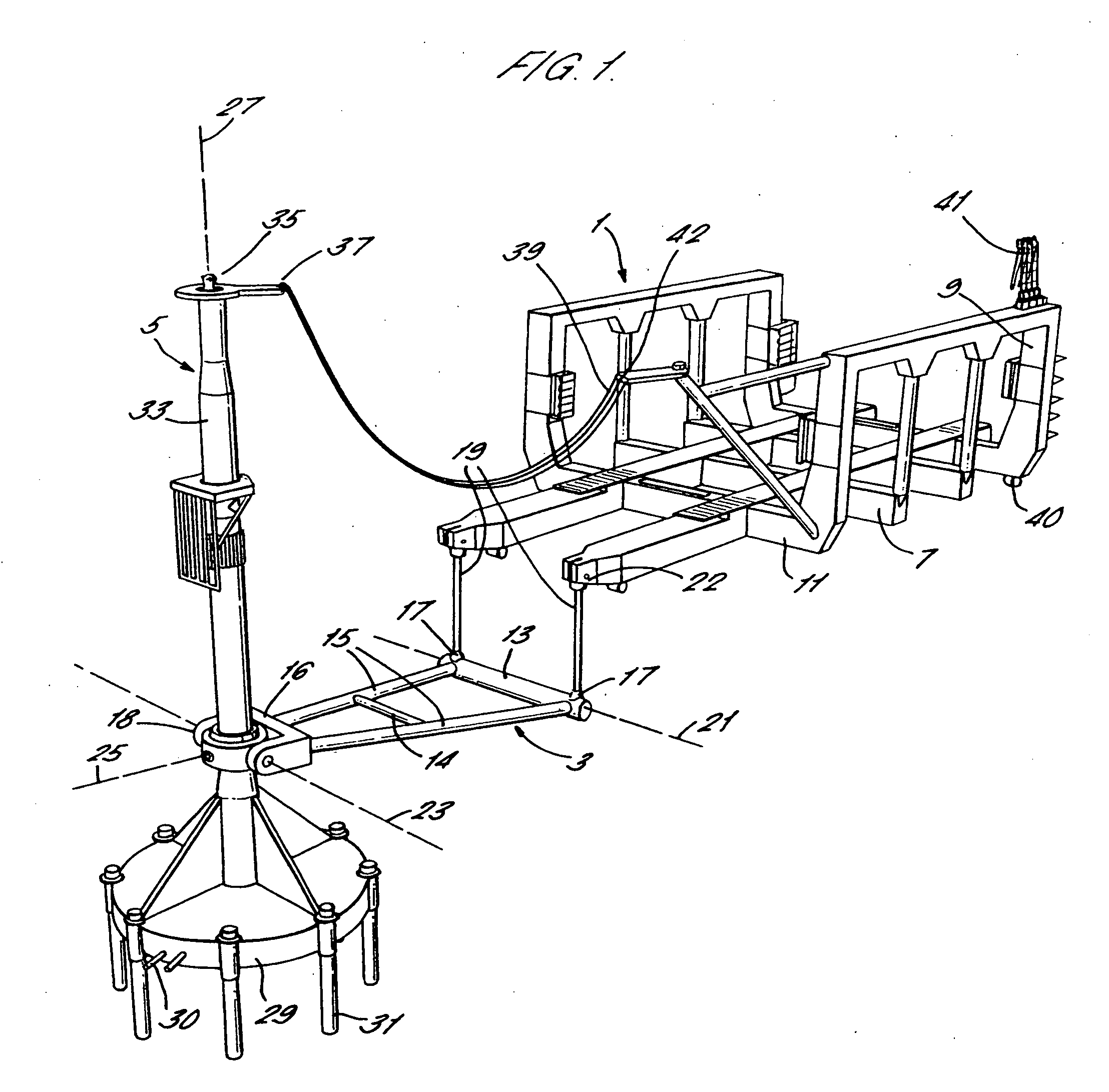
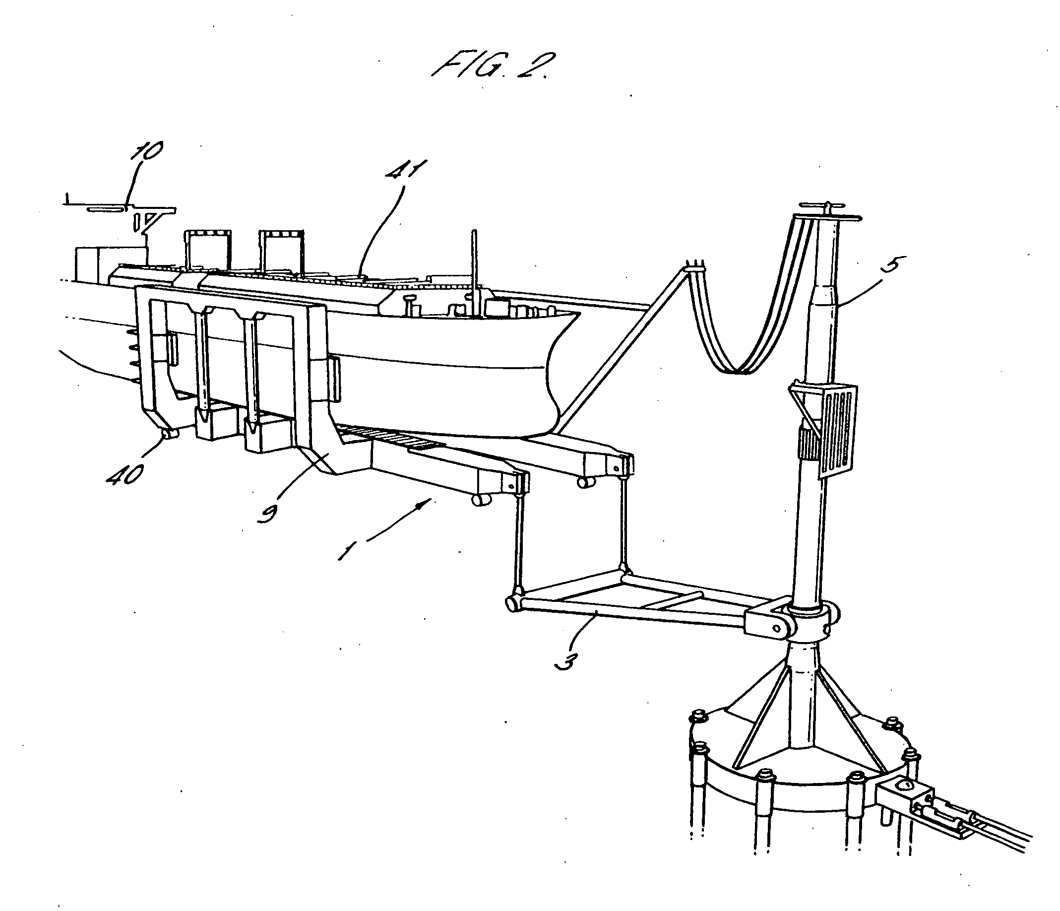
[0044] A schematic view of the apparatus according to the present invention can be seen in FIG. 1. A semi-submersible loading dock, shown generally at 1, is attached by a mooring yoke 3 to a single point mooring system, shown generally at 5. The mooring yoke 3 acts to position the loading dock 1 at a sufficient distance from the single point mooring 5 such that a vessel 10 may be positioned within the loading dock 1 without colliding with the single point mooring system 5.

[0045] In cross-section the semi-submersible loading dock 1 is arranged in a U configuration having a generally horizontal loading dock floor 7 supporting generally vertical and perpendicular uprights 9. In order to accommodate relatively slender vessels, and yet provide a large enough floor area to prevent pitching of a vessel within the loading dock 1, it is preferred that the loading dock floor 7 is rectangular in shape, with each of the longer sides oriented in a direction that is generally parallel to the side...

third embodiment

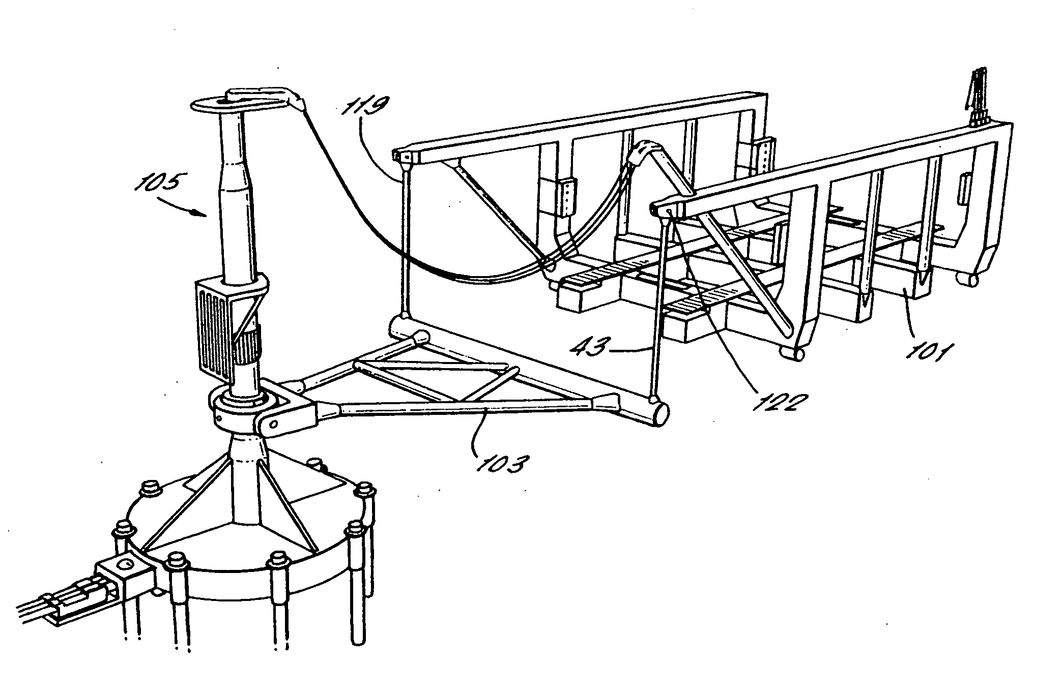
[0060] the invention is shown in FIG. 5. In this embodiment the single point mooring system to which the mooring yoke 203 is attached consists of a floating vessel 43, which itself may be moored to the seabed by means of a single point mooring. The mooring yoke 203 is attached between the vessel 43 and the loading dock 201. Provided on the hull of the vessel 43 and beneath the surface of the water is a first part 218 of a coupling to which the apex of the mooring yoke 203 is attached. Attached to the deck 45 of the vessel 43 is an upright 47 which comprises a fluid swivel 235 for connection to flexible hoses 237 as described in the previous embodiments.

fourth embodiment

[0061] the invention is shown in FIG. 6. This embodiment also comprises a floating vessel 43 attached to a single point mooring system (not shown) but utilizes two identical but handed mooring yokes 303a, 303b that are fixed to the loading dock 301 such that they may only rotate about a single generally horizontal axis 51. Each mooring yoke 303a, 303b is generally triangular and has a base 303 and two long sides 315 of unequal length. At the apex of the long sides 315 is provided a bracket 317 for attachment of a tension member 319. The base 313 acts as a hinge for connection to the floor 307 of the loading dock 301. Tension members 319 connect the mooring yokes 303a, 303b to the vessel 43 and the vessel 43 is provided with an outrigger 53 on either side of the hull for attachment of these tension member 319. The tension members 319 are attached with brackets 322 that permit them to articulate about axis 321.

[0062] The method of operation of the further embodiments of the present in...


PUM


Abstract

Apparatus is described for mooring a floating vessel (10) particularly suited to a tanker transporting liquid natural gas which needs to be moored in an offshore environment. The apparatus comprises a semi-submersible floating dock (1) a single point mooring system (5) and at least one rigid arm (3). The arm (3) is pivotally attached to one of the dock (1) and the single point mooring system (5). The arm (3) is suspended from the other of the dock (1) and the single point mooring system (5) by at least one tension member (19).

Description

BACKGROUND OF THE INVENTION [0001] 1. Field of the Invention [0002] The present invention relates to apparatus for mooring a floating vessel in open sea, using a semi-submersible floating dock. [0003] 2. General Background and State of the Art [0004] There is a fast growing demand for Liquid Natural Gas (LNG) in developed countries and as a result there is an increased need to import LNG into these countries. [0005] Unfortunately, due to the nature of LNG as a cryogenic fluid, i.e. a gas in a cooled liquid form, it is perceived that there are a number of risks associated with its handling. For this reason, it is often difficult to obtain permission for the construction and operation of LNG receiving terminals, particularly in areas that may be densely populated, either at the shore or in harbours. [0006] Alternatively, the LNG receiving terminals can be located offshore, away from any populated areas. However, transferring LNG between two offshore structures can pose a number of sig...

Claims


Application Information

Patent Timeline
IPC IPC(8): B63B21/00B63B22/02B63B27/24B63C1/04E02B3/24
CPCB63B21/00B63B22/026B63B27/24E02B3/24B63B27/34B63C1/04B63B27/30
Inventor DE BAAN, JACOB
Owner BLUEWATER ENERGY SERVECES BV
Why Eureka
Try Eureka