Stackable paperboard container

a stackable container and paperboard technology, applied in the field of containers, can solve the problems of consuming a substantial amount of material in its construction, the force of loading and stacked containers,

Inactive Publication Date: 2005-07-07
INT PAPER CO
View PDF27 Cites 33 Cited by
  • Summary
  • Abstract
  • Description
  • Claims
  • Application Information

AI Technical Summary

Benefits of technology

[0013] The container of the invention is substantially the same as the container disclosed in applicant's above-identified copending application, except that the roll-over panels and stacking tabs are on the end walls rather than the side walls. The location and capture of the extension flaps on the ends of the roll-over panels and the side walls is also reversed from that in the prior copending application. The relocation and reversal of parts from the prior container to the arrangement of the present invention provides all the advantages of the prior arrangement, i.e., the present container is stackable, structurally rigid, easy to set-up, reliably remains in set-up condition, and requires a minimum amount of material in its construction. In the particular embodiments disclosed herein, the end walls are of double wall construction, formed by inner and outer roll-over panels, and first flap extensions on opposite ends of the inner roll-over panels are folded inwardly and lie against the inner surface of the side walls. Second flap extensions on opposite ends of the side wall panels are folded inwardly and captured between the inner and outer roll-over panels. The first flap extensions are joined to the ends of the inner roll-over panel by a pair of spaced parallel folds, forming a diagonal panel in each corner of the container. These diagonal panels provide reinforcement and lend substantial stacking strength to the container. First tabs extend upwardly from the upper edge of the outer roll-over panels in spaced relationship along their length, and second tabs on the captured second flap extensions extend upwardly through the upper edge of the end walls and lie against the first tabs to form reinforced double thickness stacking tabs on the upper edge of the end walls. The walls incorporating the roll-over panels and stacking tabs, in this case the end walls, are inwardly inclined from about 2E to about 4E, whereby when two containers are placed in end-to-end abutting relationship with one another, space is formed between the abutting walls for circulation of cooling air. Notches in the upper edges of the side and end walls, and in some embodiments openings in the field of the walls, provide ventilation for circulation of cooling air through the container and produce held therein.
[0016] In a second embodiment, lid panels are foldably joined to an upper edge of each of the side wall panels, and these lid panels are folded inwardly to lie over adjacent upper edges of the end walls, completely closing the top of the container. The lid panels are held in their inwardly folded closed position by engagement of the stacking tabs in notches in the end edges of the lid panels. To accomplish this, opposite side edges of the stacking tabs are undercut, and the edges of the notches in the lid panels engage in these undercut portions. The edges of the stacking tabs above the undercut portions are inwardly tapered to facilitate downward movement of the lid panel notches over the stacking tabs.
[0019] Containers made in accordance with the invention are very strong, having excellent structural rigidity and stacking strength, and use approximately 11% less material than conventional containers. They are simple in construction, can be easily set up by hand, and once set up reliably remain in set-up condition.

Problems solved by technology

Further, the loaded and stacked containers are subjected to considerable forces during shipment and handling, and must have sufficient structural strength and rigidity to withstand these forces.
The container in U.S. Pat. No. 5,458,283 utilizes multiple reversely folded panels, and thus consumes a substantial amount of material in its construction.

Method used


Image

  • Stackable paperboard container
  • Stackable paperboard container
  • Stackable paperboard container

Examples


second embodiment

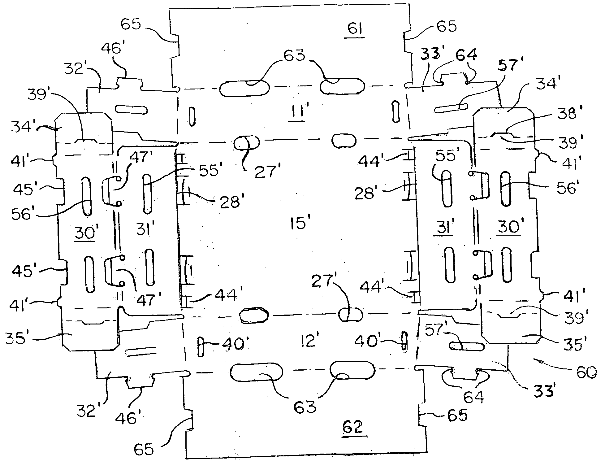
[0054] the invention is indicated generally at 60 in FIGS. 13-18. This form of the invention is essentially the same as that previously described, including the inward inclination of the indexing walls, and like or similar components are identified with like reference characters primed. Therefore, a detailed description of all the components is not provided, since it is believed that the structure and function of the components of container 60 can readily be understood by reference to the drawings and comparison of the primed reference characters with those used in describing the previous embodiment.

[0055] The container 60 differs from that previously described primarily in that it has lid panels 61 and 62 that are folded inwardly over the top of the container from opposite sides to completely cover the top of the container. Further, ventilation openings 63 span the fold joining the lid panels to the side walls, and these ventilation openings extend into the lid panels and into the ...

third embodiment

[0058] the invention is indicated generally at 70 in FIGS. 19-21. This form of the invention is essentially the same as that shown in FIGS. 13-18, except that the lid panels 71 and 72 extend only part way across the top of the container when the lid panels are closed, and bendable flaps 73 on the ends of the lid panels fold down to lie against the outer surface of the end wall when the lid panels are closed. A shaped cut 74 at the fold 75 joining the respective flaps 73 to an associated lid panel defines a reversely extending heel tab 76 that projects upwardly from each flap to lie against an outer surface of an adjacent stacking tab 20″-23″. In addition, a cut-out 77 spans the fold between the inner and outer roll-over panels 30″, 31″ to form a recessed ventilation opening 78 in the top edge of each end wall in an area lying between the confronting edges of the lid panels when they are in closed position. Further, the ventilation openings 24″ in the end walls are circular in shape ...


PUM


Abstract

A paperboard container folded from a single unitary blank of paperboard has a bottom wall, opposite side walls, and opposite end walls. Stacking tabs project from an upper edge of the end walls for receipt in corresponding slots in end edges of the bottom wall of an adjacent stacked container, and ventilation openings are formed in the side and end walls for circulation of air. The end walls are formed by inner and outer roll-over panels, and are slightly inwardly inclined to provide space for circulation of air between the containers when two of them are abutted together in end-to-end relationship. First extension flaps on the ends of the inner roll-over panels lie against and are secured to the inner surface of adjacent side walls, and second extension flaps on the ends of the side walls extend between and are captured by the inner and outer roll-over panels. In a preferred embodiment, the first extension flaps and the roll-over panels are held in place by interengaged detent tabs and slots.

Description

[0001] This application is a continuation-in-part of application Ser. No. 10 / 287,420, filed Nov. 4, 2002, which claims the benefit of US provisional application Ser. No. 60 / 336,486, filed Nov. 2, 2001.BACKGROUND OF THE INVENTION [0002] 1. Field of the Invention [0003] The present invention relates to containers in general, and more specifically to stackable containers made of paperboard. In particular, the present invention relates to a ventilated stackable container that is easy to set up, has good structural rigidity, and uses less material in its construction than conventional containers. [0004] 2. Prior Art [0005] Containers made of paperboard, i.e., corrugated cardboard, are commonly used in the produce industry to pack, store and ship fresh produce. These containers typically have a bottom, opposite side walls, opposite end walls, and either a closed or an open or partially open top, and when filled with fresh produce are placed on a pallet for shipping and handling. A standar...

Claims


Application Information

Patent Timeline
Patent Type & Authority Applications(United States)
IPC IPC(8): B65D5/00
CPCB65D5/0025B65D21/0212B65D5/0045Y10S229/916Y10S229/918
Inventor CONWAY, DOYLE A.
Owner INT PAPER CO
Why Eureka
Try Eureka