Mobile antenna system for satellite communications

a satellite communication and mobile antenna technology, applied in the field of mobile antenna systems, can solve the problems of increasing the average level of the sidelobe of the radiation pattern, too large and height of the mechanically steerable reflector antenna, and unable to meet the needs of mobile applications, etc., and achieve the effect of no gaps

Active Publication Date: 2005-07-07
GILAT SATELLITE NETWORKS
View PDF15 Cites 39 Cited by
  • Summary
  • Abstract
  • Description
  • Claims
  • Application Information

AI Technical Summary

Benefits of technology

[0013] Still further, the invention provides an antenna system comprising: at least two antenna arrangements each accommodating a transverse axis; a mechanism for rotating the arrangements in order to track a target in the azimuth plane, and rotating each arrangement about its ...

Problems solved by technology

The mechanically steerable reflector antenna has a relatively large volume and height, which, when enclosed in the necessary protective radome for mobile use, is too large and undesirable for some mobile applications, especially for ground vehicles.
Generally this is a disadvantage becaus...

Method used


Image

  • Mobile antenna system for satellite communications
  • Mobile antenna system for satellite communications
  • Mobile antenna system for satellite communications

Examples


Embodiment Construction

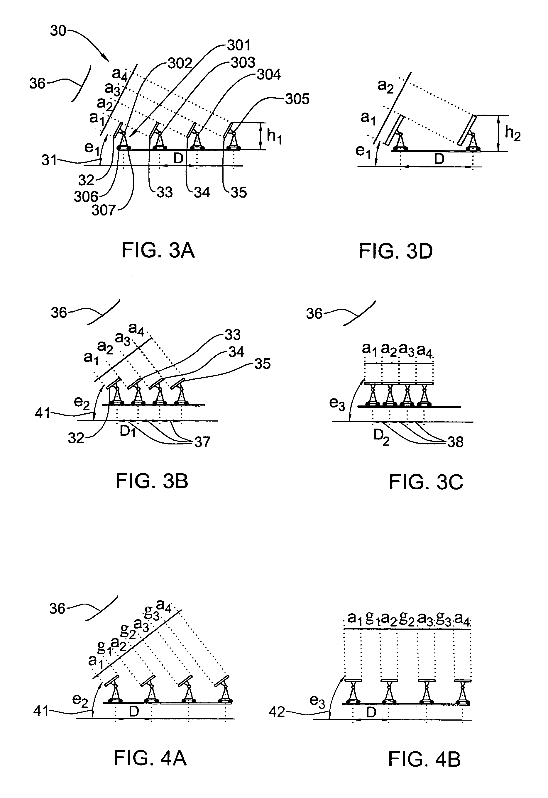
[0025] Turning now to FIG. 3A-C, there is shown, schematically a side view of an antenna unit with four antenna arrangements in different elevation angles, in accordance with an embodiment of the invention. Thus, FIG. 3A represents the case of the low elevation angle e1 31. The antenna unit 30 has four arrangements 32-35 with corresponding projection a1-a4 (where a1 is a corresponding projection of antenna arrangement 31, a2 is corresponding projection to antenna arrangement 32, and so forth). The projections are seen as continuous aperture (a1 to a4) from the observation angle of the satellite 36. Note that the distance between each two respective antenna arrangements is D. As Shown in FIG. 4a, when the elevation angle is increased to, say e2 (41) (e2>e1) but the distance between the arrangements D remains the same, certain gaps, g1-g3 appear between the apertures a1-a4 (as viewed from the observation angle of the satellite 36). As specified above, these gaps cause an increase in t...


PUM


Abstract

Antenna system that includes a plurality of antenna arrangements, each having one or more ports, and all ports connected through transmission lines in a combining/splitting circuit. The antenna arrangements form a spatial phased array able to track a satellite in an elevation plane by mechanically rotating the antenna arrangements about transverse axes giving rise to generation of respective elevation angles and changing the respective distances between the axes in a predefined relationship with the respective elevation angles. The combining/splitting circuit provides phasing and signal delay in order to maintain pre configured radiating parameters. The arrangements can be mounted on a rotating platform to provide azimuth tracking. The system provides dynamic tracking of satellite signals and can be used for satellite communications on moving vehicles.

Description

FIELD OF TIE INVENTION [0001] The present invention relates generally to mobile antenna systems with steerable beams and more particularly to antenna systems utilizing at least partial mechanical movement for use in satellite communications. BACKGROUND OF THE INVENTION [0002] There is an ever increasing need for communications with satellites, including reception of satellite broadcasts such as television and data and transmission to satellites in vehicles such as trains, cars, SUVs etc. that are fitted with one or more receivers and / or transmitters, not only when the vehicle is stationary (such as during parking) but also when it is moving. [0003] The known antenna systems for use for mobile Direct Broadcast Satellite (DBS) reception can be generally divided into several main types. One type utilizes a reflector or lens antenna with fully mechanical steering. Another type uses phased array antennas comprised of a plurality of radiating elements. The mechanically steerable reflector...

Claims


Application Information

Patent Timeline
IPC IPC(8): H01Q1/12H01Q1/32H01Q3/08H01Q3/30H01Q21/06
CPCH01Q1/1264H01Q1/3275H01Q21/06H01Q3/30H01Q3/08
Inventor STOYANOV, ILIANBOYANOV, VICTORMARINOV, BORISLAVDERGACHEV, ZAHARITOSHEV, ALEKSANDAR
Owner GILAT SATELLITE NETWORKS
Why Eureka
Try Eureka