Apparatus, method and program for moving object detection

a technology of moving objects and apparatus, applied in the field of apparatus, a method and a program for moving object detection, to achieve the effects of high precision, easy determination of the symmetry of the histogram, and high precision

Active Publication Date: 2005-07-07
HONDA MOTOR CO LTD
View PDF11 Cites 189 Cited by
  • Summary
  • Abstract
  • Description
  • Claims
  • Application Information

AI Technical Summary

Benefits of technology

[0024] By using this system construction, it is possible to determine the object image area on a basis of most symmetry point in the smoothed histogram even the peak of the histogram does not coincide with the center of the moving object because the object image area determines the object image area by using the point that shows the most symmetry of the smoothed histogram.
[0025] Especially, for the case when the moving object is human, the histogram tends to have symmetry shape since the huma...

Problems solved by technology

However, as shown in the object distance image TDE denoted with (b) in FIG. 17, the improved moving object detection method may have still a problem in detecting the center of the mo...

Method used


Image

  • Apparatus, method and program for moving object detection
  • Apparatus, method and program for moving object detection
  • Apparatus, method and program for moving object detection

Examples


first embodiment

[0063] the present invention is explained in referring to the figures and equations in the following sections.

(Structure of a Moving Object Detector)

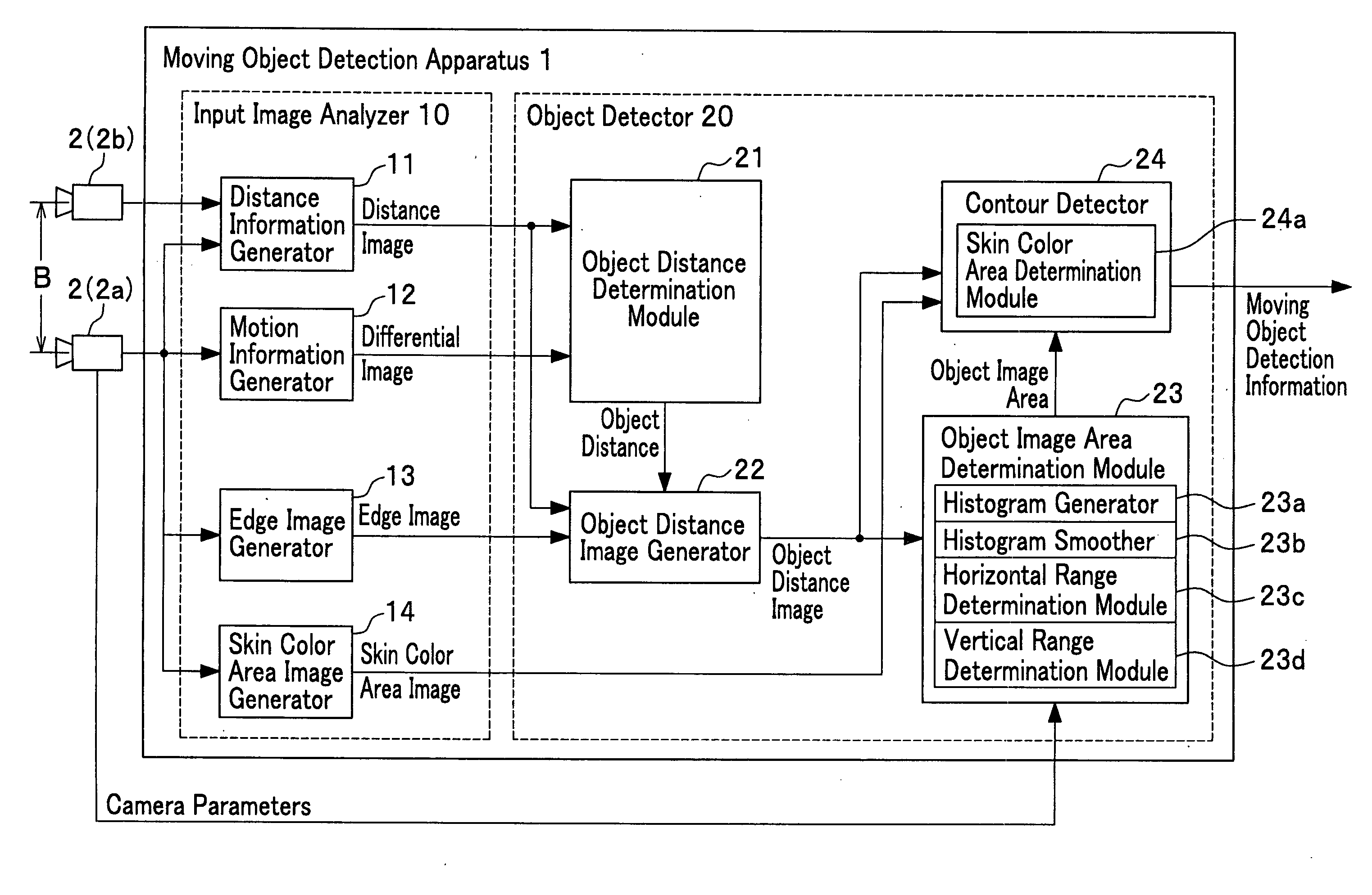
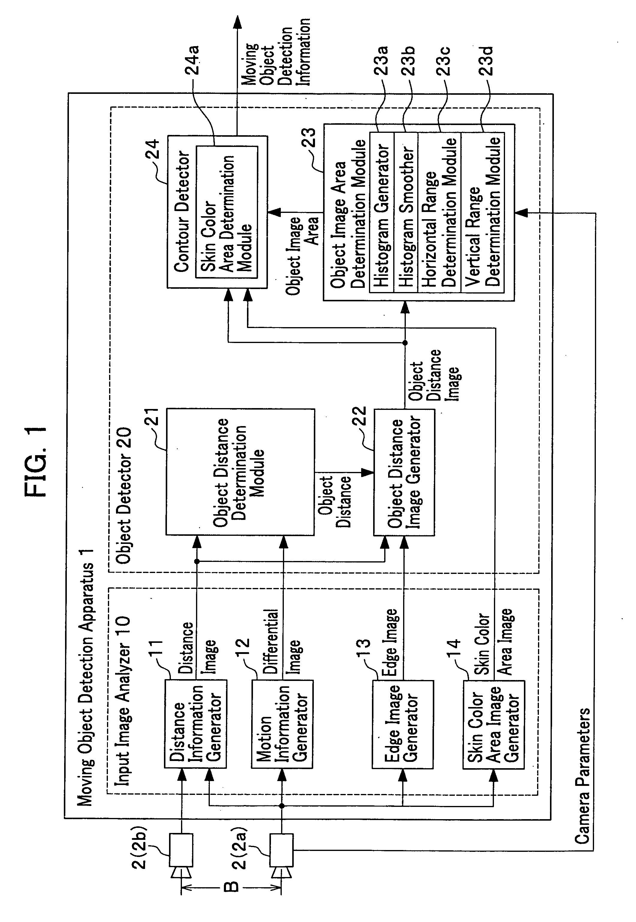
[0064]FIG. 1 shows the whole structure of the moving object detection apparatus 1. The fundamental function of the moving object detection apparatus 1 is to detect the object which is in a motion (we call “moving object”). In this embodiment, the moving object detection apparatus 1 is constructed with an input image analyzer 10 which analyzes the input video images and an object detector 20 which detects the object from the analyzed video images. Two cameras 2 composing the camera 2a and the camera 2b are horizontally set in a separation length B. One is called a right camera 2a set in relatively right position and the other a left camera 2b set in the relatively left position.

[0065] The input image analyzer 10 analyzes the video images taken by the two cameras 2 and synchronously input to the input image analyzer 10. As the result o...

second embodiment

[0172] The symmetry detector 123c detect the symmetries of the histogram HI′ for every three sequential points on the basis of the points (Xn, Sxn′) for the changing point Pn determined by the changing point detector 123b. The second embodiment specifies the difference DS of the pixel numbers for both ends of the three sequential points (we simply call “pixel number difference DS”) . A symmetry parameter is defined by the difference DK of two inclinations (which we simply call the inclination difference DS) : one between the center point and one of the neighboring points and the other between the center point and the other neighboring point.

[0173] The pixel number difference DSn is given by eq. (17) as

DSn=|SXn+2−SXn′|.  (17)

The inclination difference DKn is given by eq. (18) as

DKn=|Kn+1−Kn|,  (18)

where, the inclination is defined by

Kn=|SXn+1′−SXn′| / |Xn+1−Xn|.  (19)

[0174] The above equations are explained by using FIG. 13. The symmetry detector 123c first compute the pixel nu...


PUM


Abstract

The present invention detects a moving object by generating the distance information of the moving object, detecting the object motion, determining the object distance, detecting the object image area and the object contour from the video image that includes the object image and contour, and provides a moving object detection apparatus to carry out such detection as well as detecting a contour of the specific moving object by detecting the center of the moving object in high precision.

Description

FIELD OF THE INVENTION [0001] The present invention relates to an apparatus, a method and a program for moving object detection, more specifically, to an apparatus, a method and a program for detecting moving objects such as humans and robots by using images (namely, video images) taken by plural digital video cameras. [0002] As the technologies for detecting objects by using the video images taken by CCD video cameras, a dynamic contour model (called SNAKES), for example, that is to detect the contour of the object which is initially vague in the images, is a well known technology. The object detection technology on the basis of the contour detection is to detect the moving body by using the time-series images where a contour model is linked to the edges of the moving objects (see reference 1). [0003] The technology described in the reference 1 has a problem such that plural objects are recognized as a single body when the plural objects are neighboring each other. [0004] For such ...

Claims


Application Information

Patent Timeline
IPC IPC(8): G06K9/00G06K9/62G06T7/20
CPCG06K9/00362G06T7/2046G06T7/2053G06T2207/30196G06T2207/10016G06T2207/10028G06T7/2086G06T7/251G06T7/254G06T7/285G06V40/10
Inventor HIGAKI, NOBUOSHIMADA, TAKAMICHI
Owner HONDA MOTOR CO LTD
Why Eureka
Try Eureka