Liquid injection system having liquid injector capable of optically reading two-dimensional code assigned to liquid syringe

a liquid injection system and injector technology, applied in the field of liquid injection systems, can solve the problems of unavoidable inappropriate product use for a peripheral device such as an extension tube, inability to prevent medical errors of reusing once-used liquid syringe, and difficulty for operators who are not skilled in the work

Inactive Publication Date: 2005-07-07
NEMOTO KYORINDO KK
View PDF23 Cites 117 Cited by
  • Summary
  • Abstract
  • Description
  • Claims
  • Application Information

AI Technical Summary

Benefits of technology

[0023] In this regard, the liquid syringe has two-dimensional codes representing predetermined data items, recoded thereon, and the liquid injector is provided with a code-reading means, a code-decoding means and an operation-controlling means. The code-reading means optically reads the two-dimensional codes, and the code-decoding means decodes the optically read two-dimensional codes. The operation-controlling means executes predetermined operations corresponding to the decoded results of the two-dimensional codes. Accordingly, recording, for example, a variable pattern for liquid injection etc. in terms of two-dimensional codes in the liquid syringe makes it possible for the liquid injector to inject the liquid in accordance with the predetermined variable pattern, thereby allowing an easy input of a great amount of data to the liquid injector and enabling execution of various kinds of operations.

Problems solved by technology

Since, however, a liquid syringe has the same appearance regardless of the kind of the liquid, the operator might deploy a liquid syringe for inappropriate liquid in a liquid injector.
However, a current liquid injector cannot prevent medical errors of reusing once-used liquid syringe.
However, it might be unavoidable that an inappropriate product will be employed for a syringe peripheral device such as an extension tube or catheter
Still further, while it is necessary to enter to the liquid injector as data, the injection rate and injection amount depending on the liquid to be used, such a work is complicated and difficult to the operators who are not skilled in the work.
Consequently, it is unavoidable that inappropriate numerical values might possibly be entered.
Such a work is also complicated and it is impossible to obviate an input error.
However, it is no easy task to establish the data of such a variable pattern in a liquid injector.

Method used


Image

  • Liquid injection system having liquid injector capable of optically reading two-dimensional code assigned to liquid syringe
  • Liquid injection system having liquid injector capable of optically reading two-dimensional code assigned to liquid syringe
  • Liquid injection system having liquid injector capable of optically reading two-dimensional code assigned to liquid syringe

Examples


embodiment 100

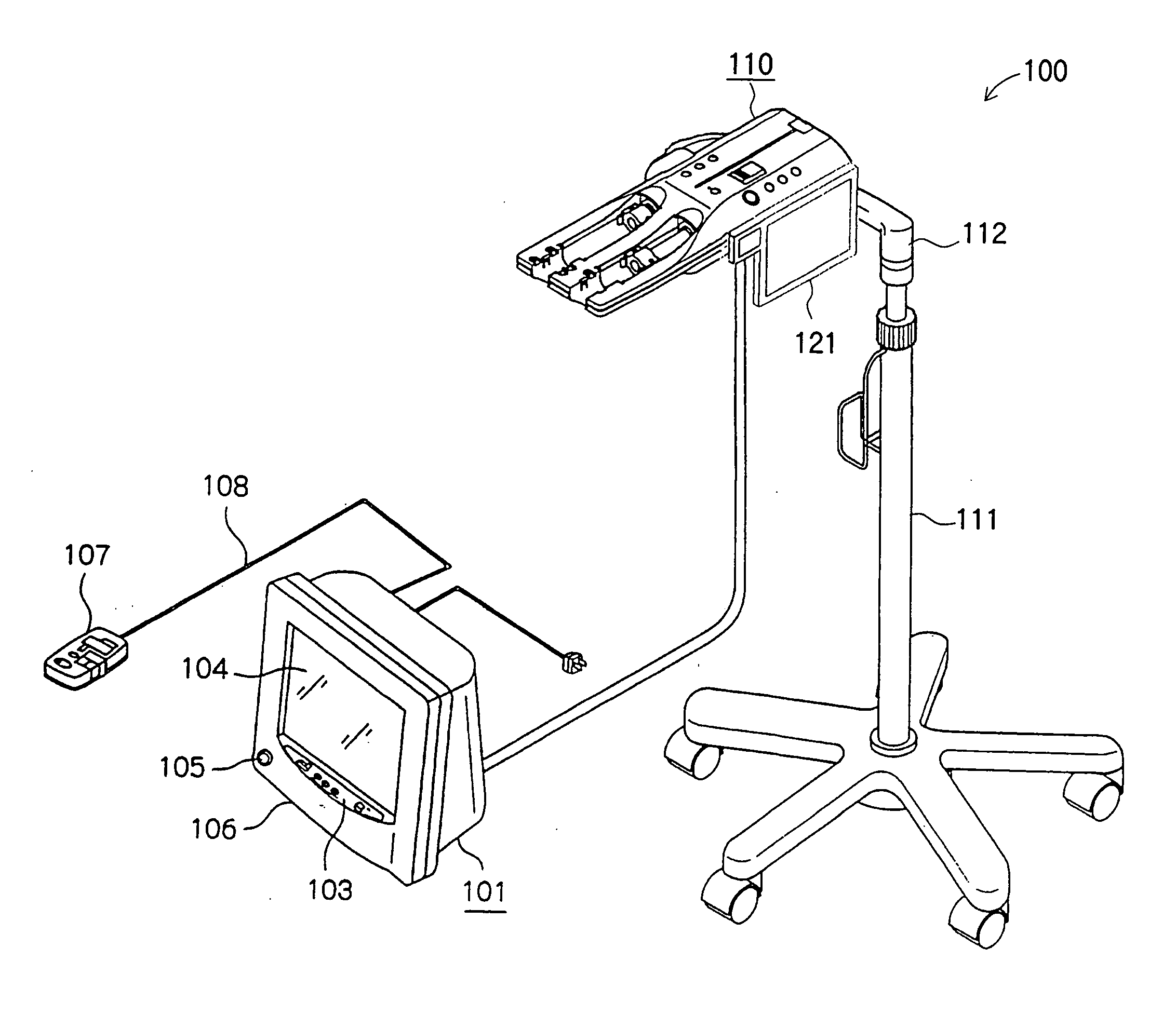
[0044] As shown in FIG. 3, liquid injector 100 of the present embodiment 100 has injection control unit 101 and injection head 110 constructed as separate units, which are wired-connected through communication cable 102.

[0045] Injection head 110 drives installed liquid syringe 200 to inject a liquid to a patient, and injection control unit 101 controls the operation of injection head 110. For this end, computer unit 130 is built in injection control unit 101 as shown in FIG. 2, and injection control unit 101 is wired-connected to imaging control unit 302 of MRI apparatus 300 through communication network 304.

[0046] Injection control unit 101 has main operation panel 103, main touch panel 104, which is a means for displaying data, speaker unit 105, etc. arranged on the front face of main body housing 116 and is wired-connected via joining connector 108 to control unit 107, which is a separate unit.

[0047] Injection head 110 is attached to the top end of caster stand 111 with movable...

embodiment 1000

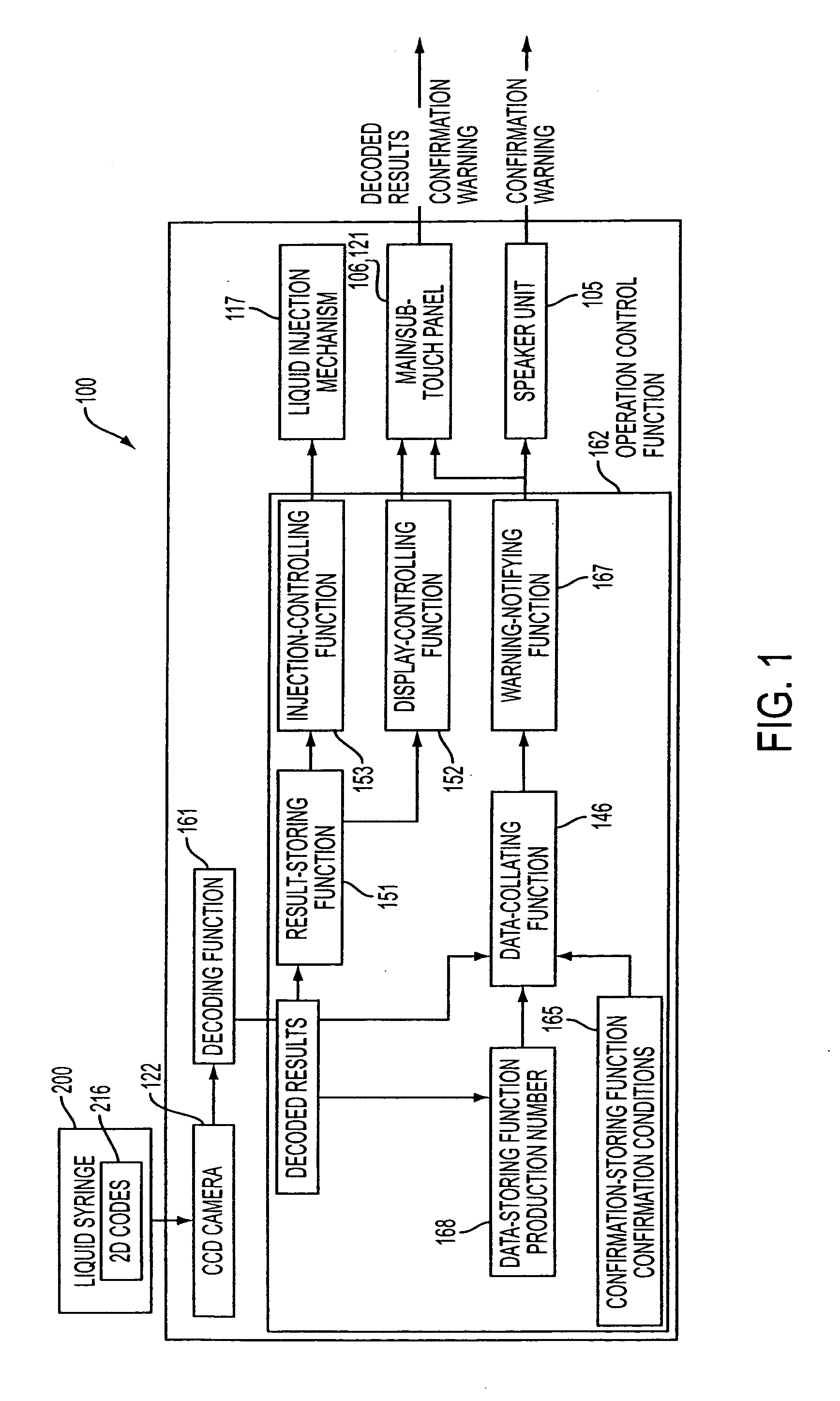
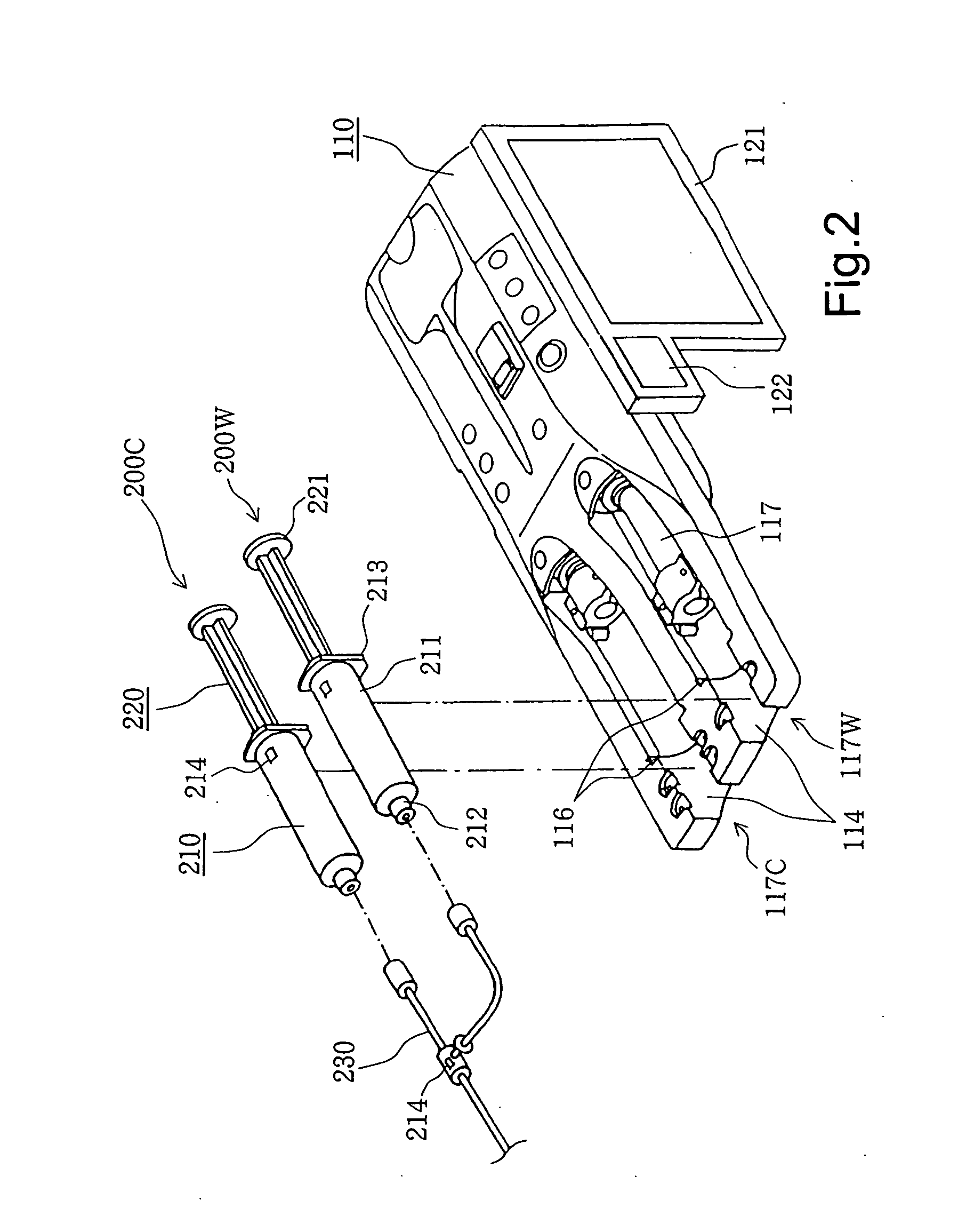
[0099] In liquid injection system of the present embodiment 1000, a sequence of the operations of recording a variety of items of data in the 2D codes 214 on liquid syringe 200, optically reading 2D codes 214, decoding them, and executing predetermined operations by liquid injector 100 makes it possible to enter a great amount of data to liquid injector 100 and execute a variety of operations.

[0100] Particularly, because 2D code 214 has a large code capacity as compared with a bar code, it is possible to save a variety of items of data together with their identification codes in liquid injector 100 in advance, there is no need to retrieve the saved data using the identification code decoded from a bar code, and even a great amount of completely new data can easily be entered to liquid injector 100.

[0101] Furthermore, in liquid injection system 1000 of the present embodiment, it is possible for an operator to confirm simply and reliably a variety of items of data about liquid syring...


PUM


Abstract

The liquid syringe has various kinds of data items recorded in the two-dimensional code format. The liquid injector optically reads the two-dimensional codes, decodes them, and executes a predetermined operations corresponding to the decoded results. Recording, for example, a variable pattern for the liquid of interest in the two-dimensional code format on the liquid syringe makes it possible for the liquid injector to inject the liquid in accordance with the predetermined variable pattern.

Description

BACKGROUND OF THE INVENTION [0001] 1. Field of the Invention [0002] The present invention relates to a liquid injection system for injecting a liquid filled in a liquid syringe into a patient through a liquid injector, and particularly to a liquid injection system for injecting a contrast medium to a patient whose diagnostic image is to be taken through a diagnostic imaging apparatus such as a CT (Computed Tomography) scanner. [0003] 2. Description of the Related Art [0004] A CT scanner, an MRI (Magnetic Resonance Imaging) apparatus, a PEP (Position Emission Tomography), an ultrasonic diagnostic apparatus, a CT Angio apparatus, an MRA (MR Angio) apparatus and the like are now used as a diagnostic imaging apparatus for shooting a diagnostic image of a patient. When using the above described diagnostic imaging apparatus, injection of a liquid such as the contrast medium or physiological saline has been made, and a liquid injector adapted for automatically performing the injection has ...

Claims


Application Information

Patent Timeline
Patent Type & Authority Applications(United States)
IPC IPC(8): A61M5/00A61M5/145
CPCA61M5/007A61M5/14546A61M2209/084A61M2205/60A61M2205/6063A61M5/1456
Inventor MASUDA, KAZUMASA
Owner NEMOTO KYORINDO KK
Why Eureka
Try Eureka