Retinal flattener

a retinal flattener and retinal technology, applied in the field of retina flattener, can solve the problems of inability to use such a special device inability to achieve retinal flattening, etc., to save the duration of surgery, improve the effect of the whole operation, and reduce the operation time.

Inactive Publication Date: 2005-07-07
ZHONGSHAN OPHTHALMIC CENT
View PDF13 Cites 6 Cited by
  • Summary
  • Abstract
  • Description
  • Claims
  • Application Information

AI Technical Summary

Benefits of technology

[0012] The retinal flattener designed in the present invention solves the problems like that traumas are often caused on the retina due to lack of suitable special device during the retina reattachment in modern vitreoretinal surgery, and that the effect of the surgery may be influenced and so on. Applying the retinal flattener of the present invention in vitreoretinal surgery we can benefit from following advantages:
[0013] 1. At the later stage of tamponment of silicone oil or gas in the vitreoretinal surgery, the retina, especially the macula and some o

Problems solved by technology

There has not been such a special device available used for that operation till now.
This operation is inefficient and not very effective, and even worse, it is prone to retina hurt.
Moreover, because of the met

Method used


Image

  • Retinal flattener
  • Retinal flattener
  • Retinal flattener

Examples


example 1

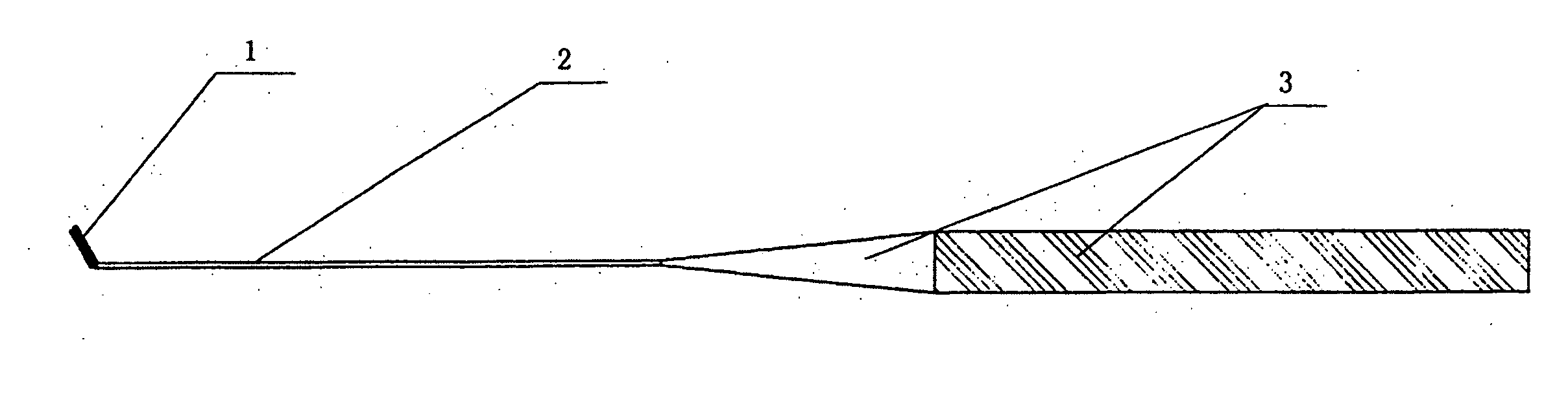
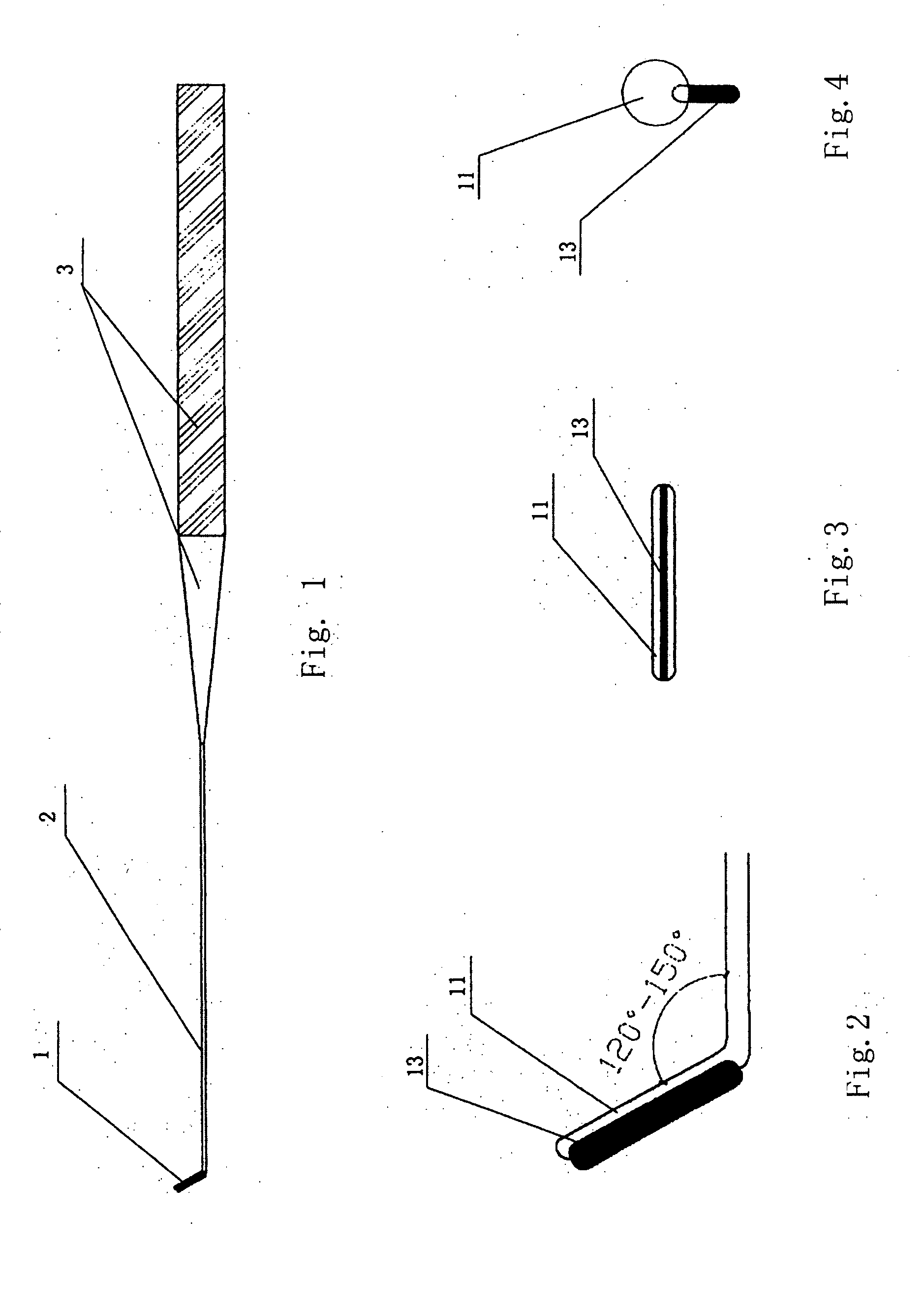
[0029] As shown in FIG. 1, the retinal flattener contains a working tip 1, a rod 2 and a handle 3, wherein the rod 2 is a metal rod made of stainless steel materials, whose diameter is 0.4 mm and length is 40 mm, and the angle between the working tip 1 and the rod 2 is 120°. The angle can be adjusted finely with hemostatic forceps in operation. The base 11 of the working tip, which is 2 mm long, is the extended part of the rod 2 with the same core (as shown in FIG. 2). A thin piece of silicone film 13, shaped like a brush, is inlaid underside the base 11 as a soft pressing working element. The soft silicone film 13 is 0.1 mm thick and the portion extended from the base dimensions 0.3 mm (as shown in FIGS. 3 and 4). The total length of the retinal flattener is about 110 mm.

[0030] When applying the retinal flattener in operation, at first an operator adjusts the angle of the working tip with hemostatic forceps according to the different areas rubbed down, and then, in order to flat t...

example 2

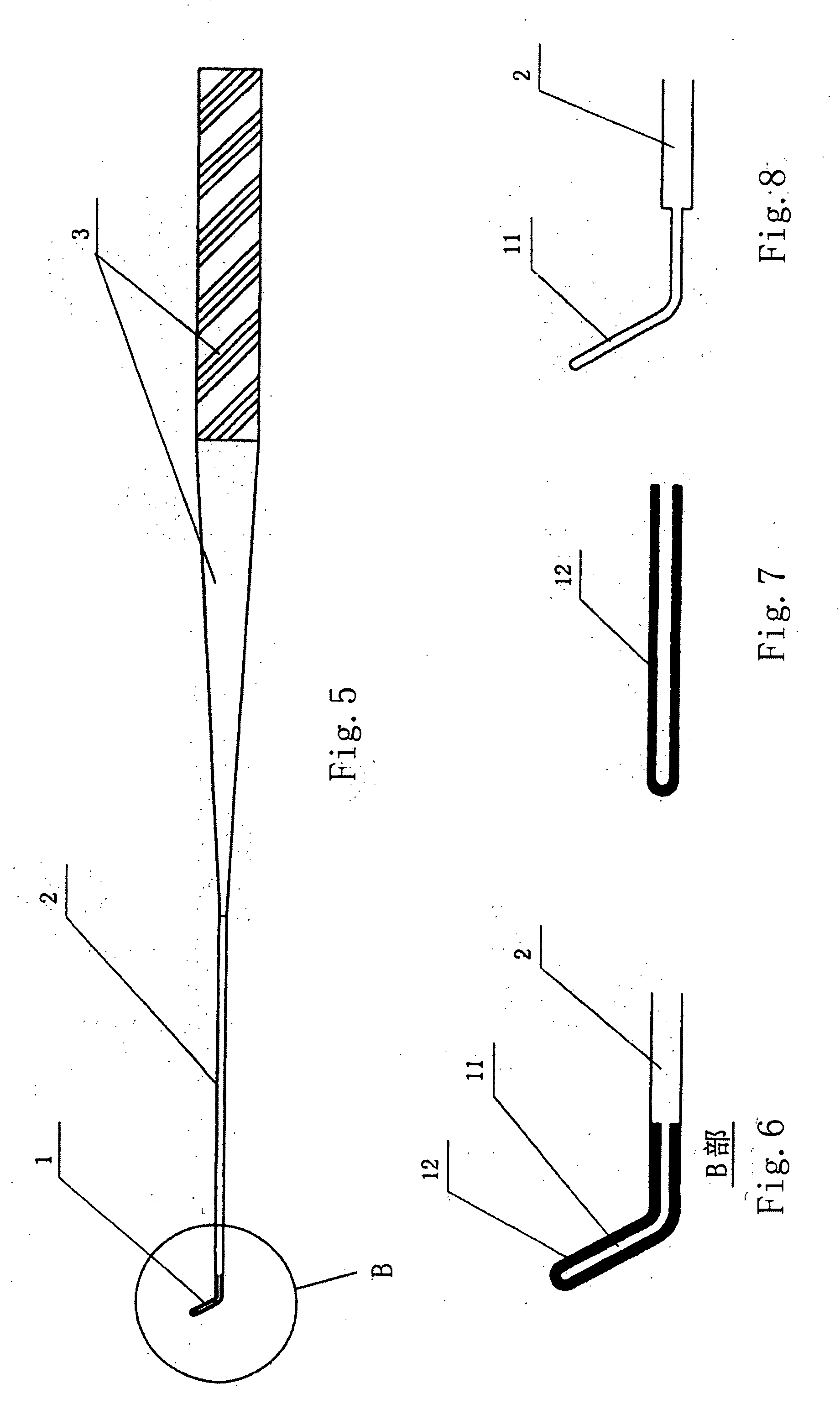
[0031] As shown in FIG. 5, the retinal flattener contains a working tip 1, a rod 2 and a handle 3, wherein the rod 2 is a metal rod made of stainless steel materials, whose diameter is 0.8 mm and length is 30 mm, and the angle between the working tip 1 and the rod 2 is 120°. The angle can be adjusted finely with hemostatic forceps in operation. The soft pressing element of the working tip is a silicone tube 12 covered over the base, whose wall is 0.2 mm thick (as shown in FIG. 7). The base of the working tip, whose diameter is about 0.4 mm, can be the core 11 of the contracted rod extended from the front end of the rod (as shown in FIG. 8). The total external diameter of the working tip equals to the one of the rod while the silicone tube covers the base (as shown in FIG. 6). The whole retinal flattener is about 130 mm long.

example 3

[0032] As shown in FIG. 9, the retinal flattener contains a working tip 1, a rod 2 and a handle 3, and its structure is the same as the one in Example 2 on the whole. The differences is that as the soft pressing element of the working tip, the silicone tube 12 only covers the front part of the working tip (as shown in FIG. 10). The silicone tube 12 and the base 11 of the working tip are shown in FIGS. 11 and 12.


PUM


Abstract

The present invention relates to a retinal flattener, which is a medical device for retina reattachment in modern vitreoretinal surgery. The retinal flattener designed in the present invention generally contains a slender rod and a working tip at the forehead of the rod. The working tip consists of a base and a soft pressing element on the base. The special structures of the retinal flattener in the invention are designed according to the special requirement of the intraocular surgery. The form and the structure of the working tip facilitate operators to insert it into eyes from any of the two superior incisions in the modern standard three incisions vitreoretinal surgery. The soft pressing element applied in the working tip is used for retina-flatting operation such as rubdown and touch.

Description

TECHNICAL FIELD [0001] The present invention relates to a medical device for retina reattachment in modern vitreoretinal surgery. BACKGROUND OF THE INVENTION [0002] In modern vitreoretinal surgery, complete retinal reattachment is a sticking point to the success of the surgery. Along with the increasing maturation in microtechnique and the gradual growth in the understanding of the surgery, the problem how the retina, especially the macula and some other vital areas, could be better flatted and recovered after retinal detachment has a direct effect on the result of the whole surgery. [0003] There has not been such a special device available used for that operation till now. Usually most operators use available retinal picks or flute needles to draw repeatedly on the retinal surfaces for the above purpose. This operation is inefficient and not very effective, and even worse, it is prone to retina hurt. Because the retina reattachment only depends on the repeated pull and draw, the oc...

Claims


Application Information

Patent Timeline
IPC IPC(8): A61F9/00A61F9/007A61F9/013
CPCA61F9/0133
Inventor TANG, SHIBO
Owner ZHONGSHAN OPHTHALMIC CENT
Why Eureka
Try Eureka