Three-dimensional error correction method

a three-dimensional error and correction method technology, applied in the direction of digital signal error detection/correction, coding, code conversion, etc., can solve the problems of group errors to be generated, loss of repetitive correction capability, excessive increase of parity information, etc., to improve the error correction capability

Inactive Publication Date: 2005-07-07
DAEWOO ELECTRONICS CO LTD
View PDF6 Cites 70 Cited by
  • Summary
  • Abstract
  • Description
  • Claims
  • Application Information

AI Technical Summary

Benefits of technology

[0007] It is, therefore, an object of the present invention to provide a three-dimensional error correction encoding method, which performs three-dimensional error correction encoding with respect to a three-dimensional data block in horizontal, vertical and z-axial directions, thus improving error correction capability.

Problems solved by technology

In particular, damaged surfaces of magnetic tapes or discs or dust thereon may cause group errors to be generated, thus considerably requiring a Reed-Solomon (RS) code.
However, there is a problem in that, if a large number of errors exist, saturation occurs, so that error correction cannot be performed in any direction in two dimensions, thus losing repetitive correction capability, which is the best feature of the two-dimensional error correction.
Further, in the case where horizontal and vertical parity symbols are added, two-dimensional parity symbols, that is, vertical parity symbols corresponding to horizontal parity symbols, are added, so that parity information increases excessively, thus excessively increasing a code rate.

Method used


Image

  • Three-dimensional error correction method
  • Three-dimensional error correction method
  • Three-dimensional error correction method

Examples


first embodiment

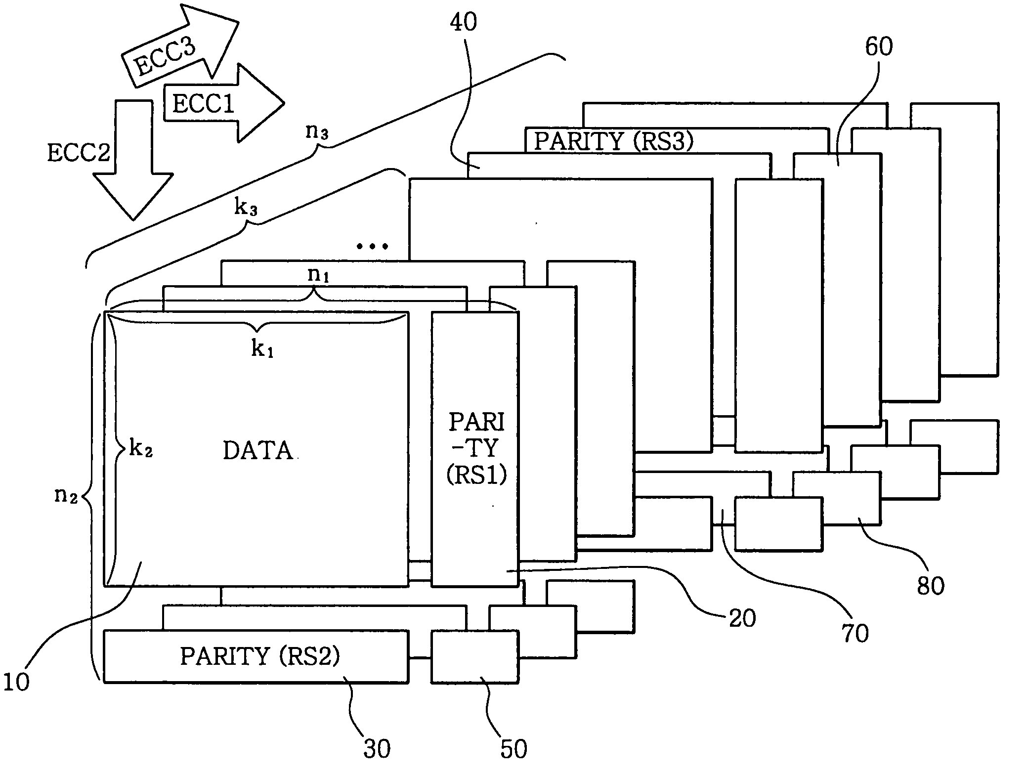
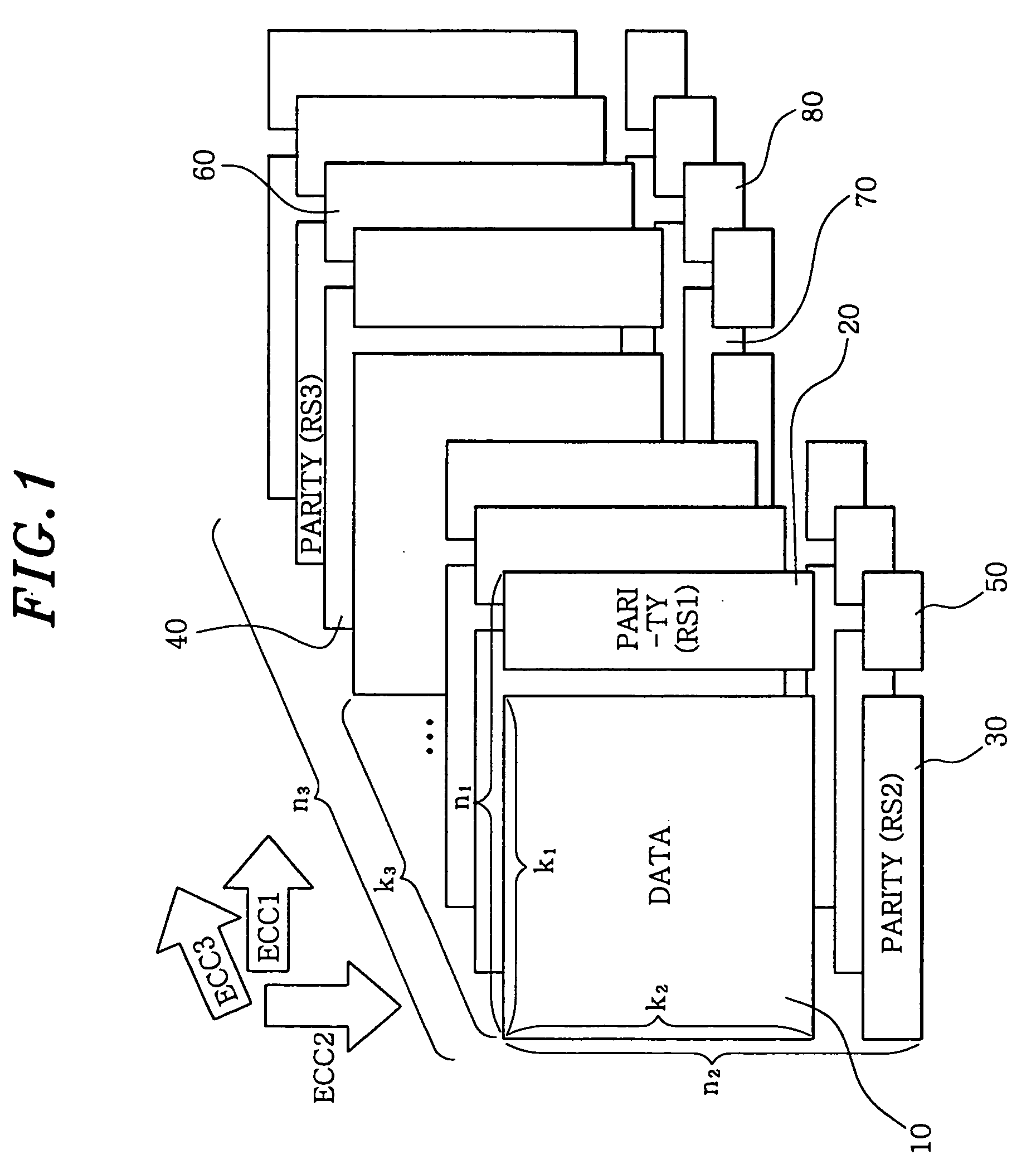
[0019]FIG. 1 illustrates a conceptual view of code construction to show an error correction encoding method using a three-dimensional (3D) Reed-Solomon code according to the present invention. As shown in FIG. 1, pieces of input information are arranged in a 3D data block 10 implemented with a (k1, k2, k3) array of information symbols, where k1, k2 and k3 are positive integers. In other words, the 3D data block 10 has a (k1, k2, k3) array structure in which k1*k2*k3 information symbols are arranged along horizontal, vertical and z-axial directions.

[0020] 3D error correction encoding is performed with respect to the 3D data block 10, so that horizontal, vertical and z-axial error correction parity symbols are added to the 3D data block 10 in horizontal, vertical and z-axial directions, respectively. In FIG. 1, the horizontal, vertical and z-axial directions are indicated by first, second and third error correction encoding axis ECC1, ECC2 and ECC3, respectively. First, n1−k1 error co...

second embodiment

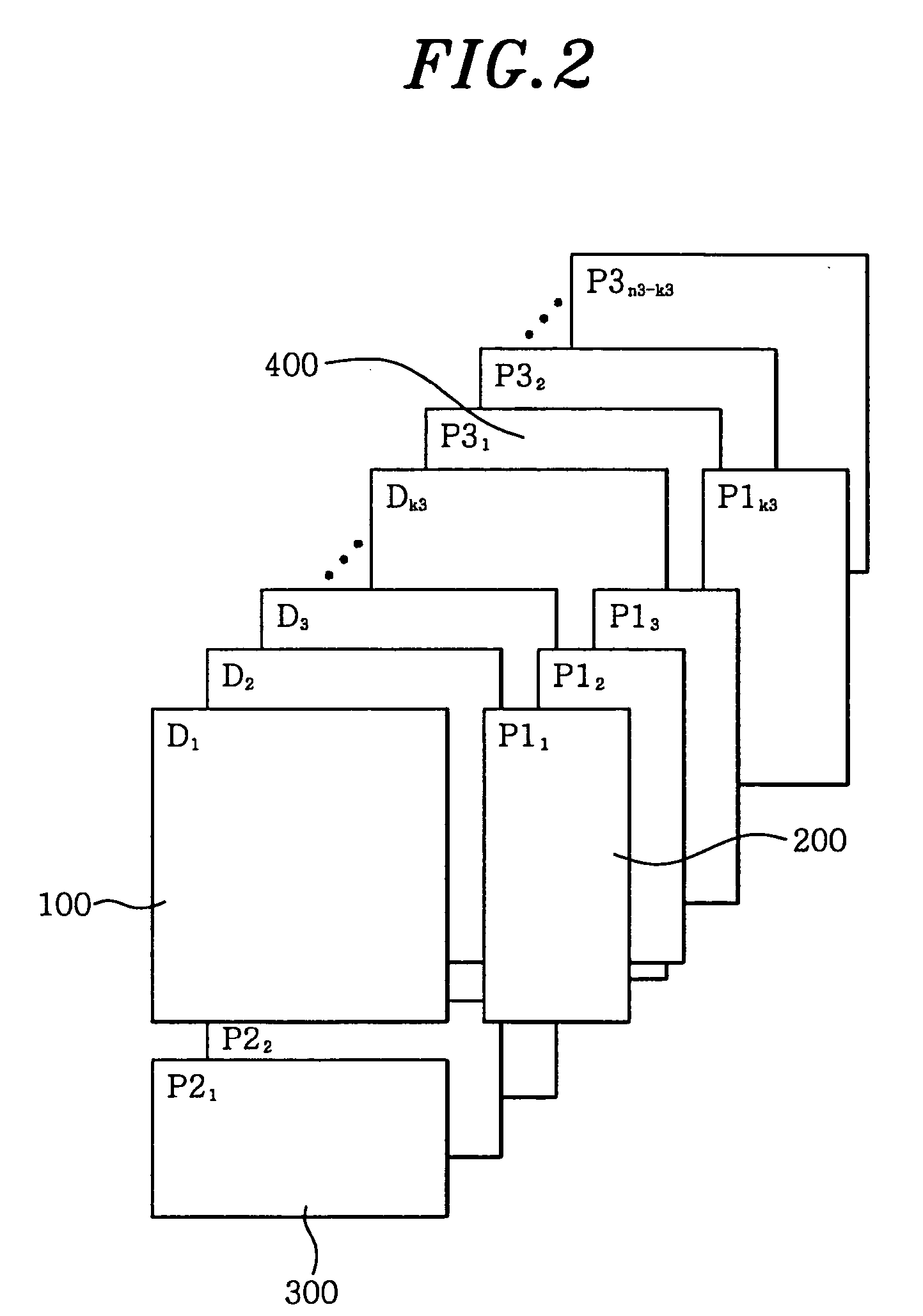
[0025]FIG. 2 illustrates a conceptual view of code construction to show an error correction encoding method using the 3D Reed-Solomon code according to the present invention.

[0026] Unlike the 3D Reed-Solomon code according to the first embodiment, a 3D Reed-Solomon code according to the second embodiment performs only error correction encoding for a (k1, k2, k3) array of information symbols itself, thus including only primary error correction parity symbols and excluding secondary and tertiary error correction parity symbols. In detail, the 3D Reed-Solomon code according to the second embodiment includes (n1−k1)*k2*k3 primary horizontal error correction parity symbols P11 to P1k3 200, k1*(n2−k2)*k3 primary vertical error correction parity symbols P21 to P2k3 300, and k1*k2*(n3−k3) primary z-axial error correction parity symbols P31 to P3n3−k3 400, in addition to a (k1, k2, k3) array of information symbols D1 to Dk3 100. In the present invention, the error correction parity symbols a...

third embodiment

[0027]FIG. 3 illustrates a conceptual view of code construction to show an error correction encoding method using a 3D Reed-Solomon code according to the present invention.

[0028] Unlike the 3D Reed-Solomon code according to the second embodiment, the 3D Reed-Solomon code according to the third embodiment is constructed in such a way that the primary error correction parity symbols generated according to the second embodiment are rearranged. For example, primary z-axial error correction parity symbols P31 to P3n3−k3 400 among (n1−k1)*k2*k3 primary horizontal error correction parity symbols P11 to P1k3 200, k1*(n2−k2)*k3 primary vertical error correction parity symbols P21 to P2k3 300, and k1*k2*(n3−k3) primary z-axial error correction parity symbols P31 to P3n3−k3 400 may be rearranged at the locations of the secondary vertical error correction parity symbols of the 3D Reed-Solomon code according to the second embodiment shown in FIG. 2. If necessary, as shown in FIG. 3, each area of...


PUM

PropertyMeasurementUnit
signal to noise ratioaaaaaaaaaa
horizontal lengthaaaaaaaaaa
vertical lengthaaaaaaaaaa

Abstract

The present invention relates to an error correction encoding method using a three-dimensional Reed-Solomon code. In the error correction encoding method, pieces of input information are arranged in a three-dimensional data block. Three-dimensional error correction encoding is performed with respect to the three-dimensional data block, thereby adding horizontal, vertical and z-axial error correction parity symbols to the three-dimensional data block in horizontal, vertical and z-axial directions, respectively.

Description

FIELD OF THE INVENTION [0001] The present invention relates to a three-dimensional error correction encoding method; and more particularly, to a three-dimensional error correction encoding method, which performs error correction coding with respect to a three-dimensional data block using one-dimensional parity in digital information devices or communication devices, thereby improving error correction capability. BACKGROUND OF THE INVENTION [0002] One parameter for determining the quality of a digital communication system is a “Bit Error Ratio (BER)”. BER is the parameter for determining the probability of occurrence of bits having an error in the output of a reception system. Storage devices, such as tapes, discs, Compact Discs (CDs), Digital Versatile Discs (DVDs) and barcodes, mobile communication devices, such as cellular phones and microwave links, satellite communication devices, and digital televisions generally require BER of 10−9 or below. [0003] In order to increase BER wit...

Claims


Application Information

Patent Timeline
Patent Type & Authority Applications(United States)
IPC IPC(8): G06F11/10G11B20/18H03M13/15H03M13/29H04L1/00
CPCH03M13/2906
Inventor HWANG, EUISEOK
Owner DAEWOO ELECTRONICS CO LTD
Why Eureka
Try Eureka