Motor for vehicle

Inactive Publication Date: 2005-07-14
TOYOTA JIDOSHA KK
View PDF13 Cites 46 Cited by
  • Summary
  • Abstract
  • Description
  • Claims
  • Application Information

AI Technical Summary

Benefits of technology

[0015] In this manner, the cooling liquid is supplied to the cooling liquid supply portion provided in the lowermost portion, for example, by means of a compression transport pump. Then, the cooling liquid passes through the cooling passage formed so as to attain contact between the cooling liquid and the stator coil, and it is discharged from the cooling liquid discharge portion provided in the uppermost portion. Here, the cooling liquid fills the lower

Problems solved by technology

In addition, in order to distribute the cooling liquid to all parts of the stator coil, it is necessary to provide a straightening vane in the cooling passage, which results in a complicated structure.
Here, air bubbles are introduced i

Method used


Image

  • Motor for vehicle
  • Motor for vehicle
  • Motor for vehicle

Examples


first embodiment

[0034] First Embodiment

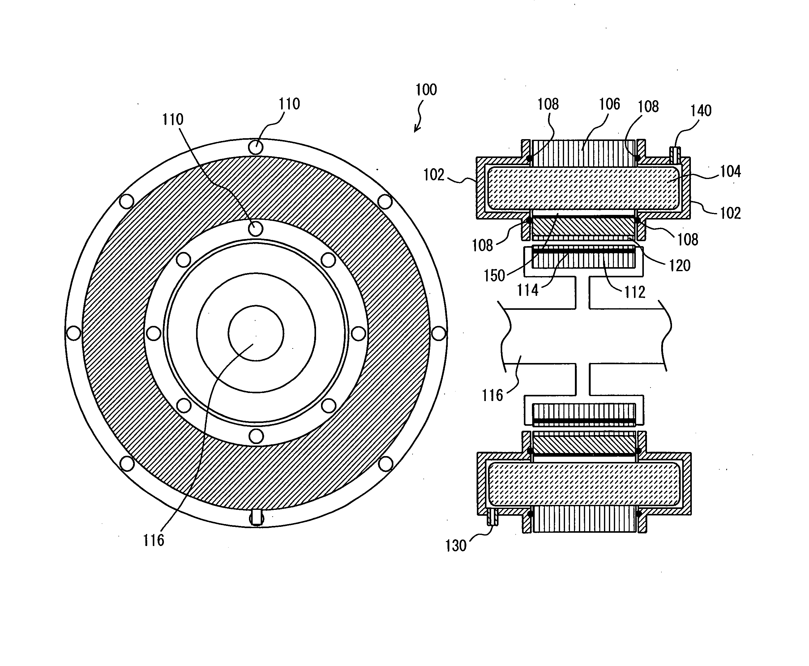
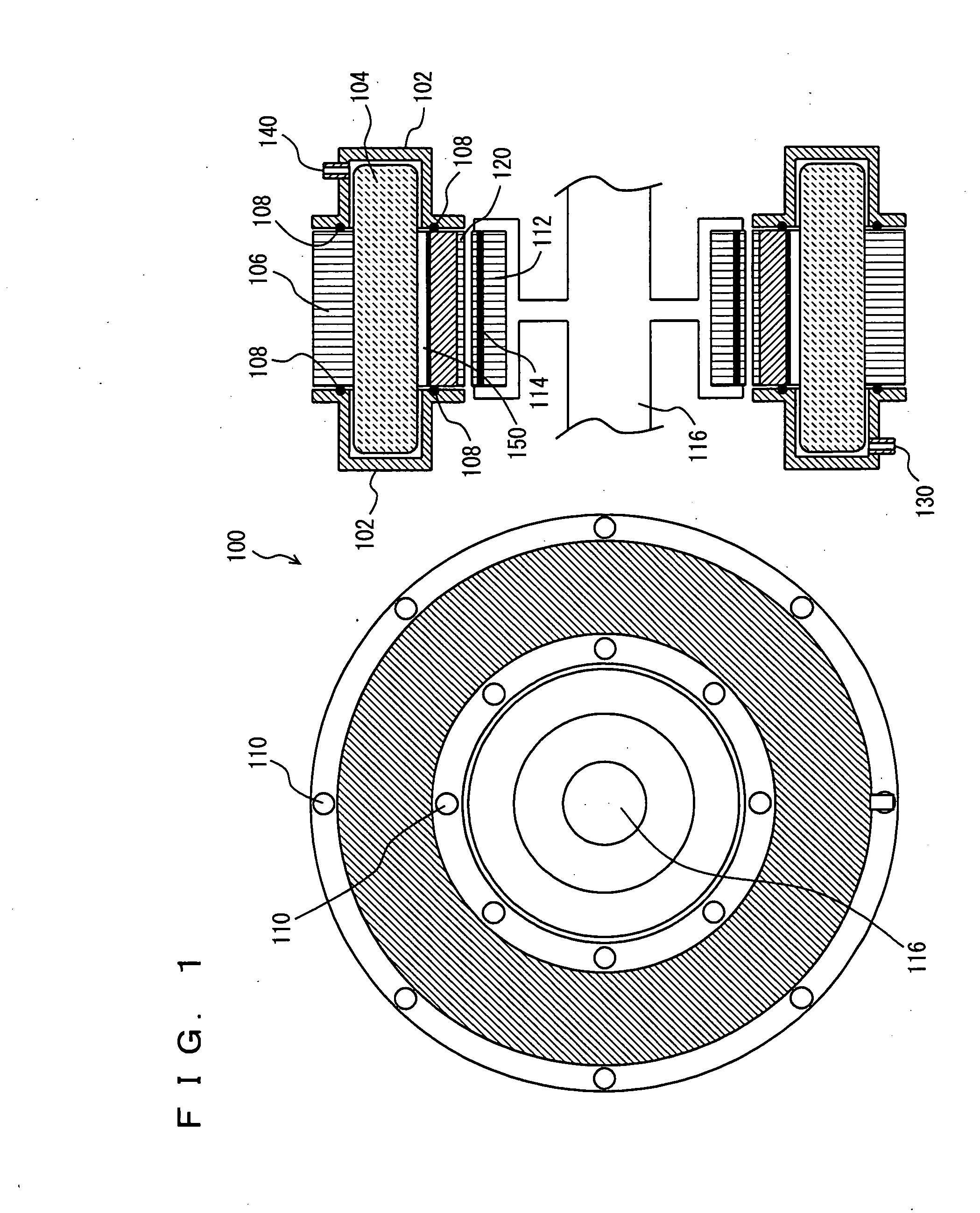
[0035] Referring to FIG. 1, a structure of a motor according to the present embodiment will be described. As shown in FIG. 1, a motor 100 is mounted on a vehicle, and used in such a manner that its rotation shaft extends in a horizontal direction. FIG. 1 shows a cross-sectional view and a side view of motor 100. Broadly speaking, motor 100 is constituted of a stator portion and a rotor portion. The stator portion includes a stator core 106 having a coil 104 wound in a slot. The stator portion is covered with a coil end cover 102 surrounding opposing end surfaces of coil 104 and stator core 106 in a cup-shaped manner.

[0036] Coil end cover 102 is provided with a cooling oil inlet 130 in its lower portion and a cooling oil discharge outlet 140 in its upper portion. Coil end cover 102 comes in contact with stator core 106, with an O-ring 108 being interposed. Coil end cover 102 is connected to stator core 106 by means of a prescribed number of bolts 110, so as to...

second embodiment

[0054] Second Embodiment

[0055] In the following, a motor and a cooling system of the same according to the second embodiment of the present invention will be described.

[0056] As shown in FIG. 5, in the cooling system of the motor according to the present embodiment, a check valve 300 is provided at cooling oil discharge outlet 140 in the cooling system of the motor according to the first embodiment described above. As the structure of the cooling system is otherwise similar to that according to the first embodiment described above, detailed description thereof will not be repeated.

[0057] Check valve 300 is provided between discharge pipe 164 and cooling oil discharge outlet 140, so as to permit oil flow only in a direction from the motor to discharge pipe 164. The cooling oil cannot flow in the opposite direction.

[0058] An operation of the cooling system of the motor according to the present embodiment will now be described. When oil pump 160 starts its operation and the cooling ...


PUM


Abstract

A motor having a rotation shaft extending in a horizontal direction and efficiently cooling stator portion includes a cooling oil inlet provided in a lower portion of the motor in order to introduce the cooling oil supplied from an oil pump through a supply pipe, a coil end cover for immersing a stator portion of the motor in order to discharge the cooling oil from the motor, and a discharge pipe connected to the cooling oil discharge outlet for discharging the cooling oil to an oil pan.

Description

TECHNICAL FIELD [0001] The present invention relates to a structure of a motor, and more particularly to a structure of a liquid-cooled motor mounted on a vehicle such as an automobile. BACKGROUND ART [0002] A motor or a generator mounted on a vehicle such as an automobile includes a rotator (a rotor) and a stator core arranged around the rotor and having a stator coil wound. The motor feeds a current to the stator coil in order to obtain a rotation force, while the generator takes out a current generated by rotation of the rotor and flowing through the stator coil. When the current flows through the stator coil in rotation of the rotor, the stator core or the stator coil generates heat. A cooling device for suppressing such heat is disclosed, for example, in Japanese Patent Laying Open No. 2001-145302. [0003] The cooling device serves as a cooling device for a motor mounted on a vehicle having a rotation shaft extending in a horizontal direction. The motor includes a rotor rotatabl...

Claims


Application Information

Patent Timeline
IPC IPC(8): H02K3/24H02K9/197
CPCH02K9/197H02K3/24
Inventor TAKETSUNA, YASUJIKATSU, TOSHIAKIHARADA, KENJI
Owner TOYOTA JIDOSHA KK
Why Eureka
Try Eureka