Cam locked air gap baffle assembly for a dynamoelectric machine

Active Publication Date: 2005-07-14
SIEMENS ENERGY INC
View PDF13 Cites 25 Cited by
  • Summary
  • Abstract
  • Description
  • Claims
  • Application Information

AI Technical Summary

Benefits of technology

[0008] The air gap barrier system may also include a locking tool for moving the locking cam assembly between an unlocked position and a locked position, or vice versa. The locking tool may be capable of actuating a plurality of locking cam assemblies simultaneously by inserting the locking tool through inner cavities of cams. The locking tool may include one or more keys extending from an outer surface. The key may be positioned and sized to fit into a keyway in an inner wall forming a cavity in a cam. In an alternative embodiment, the locking tool may include one or more keyways and a cavity in a cam may include one or more keys. In at least one embodiment, the locking tool may include two keys extending from the locking tool approximately 180 degrees apart. The keys may extend the length of the locking tool, or may be placed an intermittent locations along the length of the tool in locations corresponding to the keyways in the cams. The locking tool is preferably bendable in the radial direction to enable the tool to be bent around support structures on a dynamoelectric machine to enable the tool to be inserted through locking cam assemblies without requiring such support structures to be disassembled and removed. However, the locking tool preferably resists twisting about the longitudinal axis of the locking tool. In at least one embodiment, the locking tool is formed from a generally cylindrical shaft.
[0011] An advantage of this invention is that the cam mechanisms provide increased reliability for releasable attachment systems for air gap baffles.
[0012] Another advantage of this invention is that the friction pad and the locking strip reduce the likelihood that a locking cam mechanism will inadvertently move from a locked position to an unlocked position.
[0013] Yet another advantage of this invention is the locking tool is capable of moving a plurality of cams from unlocked positions to locked positions simultaneously, thereby enabling a user to lock all of the cam mechanisms in a shorter amount of time.

Problems solved by technology

At least one factor affecting the efficiency of dynamoelectric cooling systems is the amount of leakage past the air gap baffles.
Thus, baffles cannot be fixedly coupled to both rotors and stators.
While this system enables baffles to be locked into position, the locking system is unnecessarily complex.

Method used


Image

  • Cam locked air gap baffle assembly for a dynamoelectric machine
  • Cam locked air gap baffle assembly for a dynamoelectric machine
  • Cam locked air gap baffle assembly for a dynamoelectric machine

Examples


Embodiment Construction

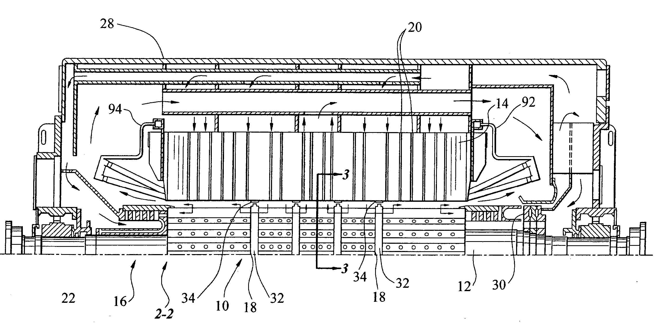
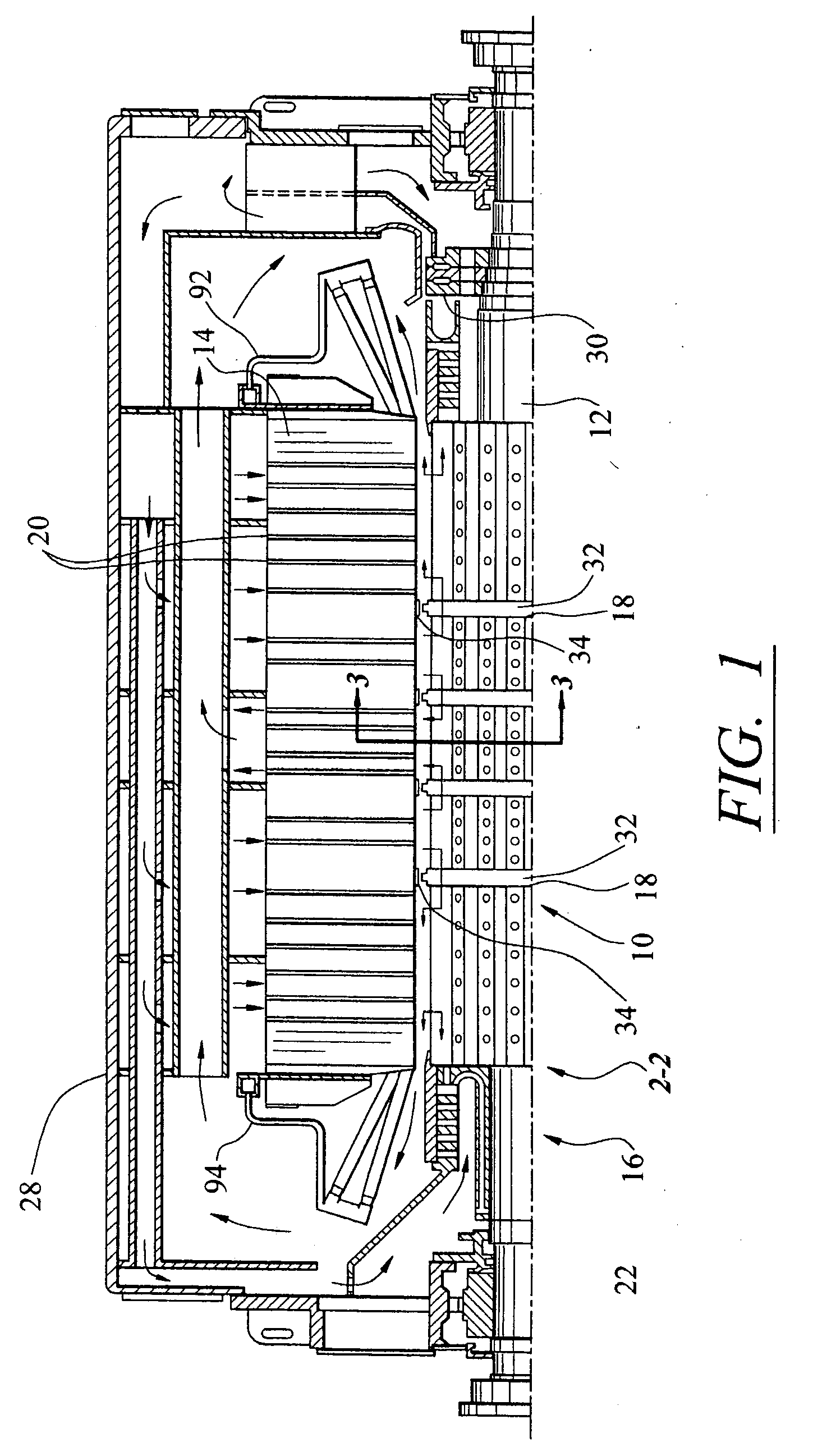
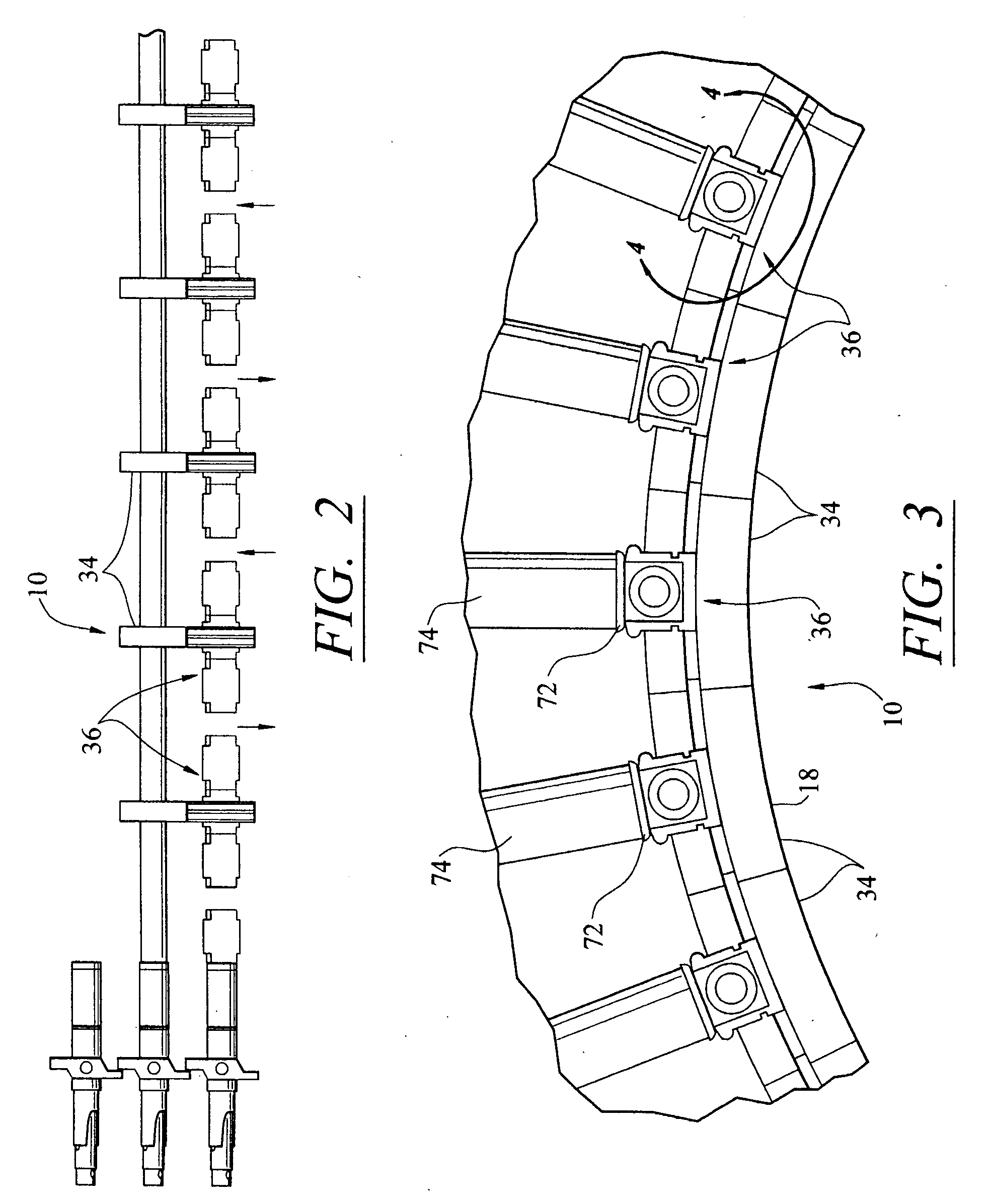
[0026] As shown in FIGS. 1-10, this invention is directed to a barrier system 10 for sealing air gaps found between stators 12 and rotors 14 in dynamoelectric machines 16. The barrier system 10 positions baffles 18 between stators 12 and rotors 14 to form a plurality of cooling pathways 20 for passing cooling fluids through the dynamoelectric machine 16 from high pressure zones to low pressure zones to cool the components thereof. The barrier system 10, in at least one embodiment, is configured to facilitate easy installation and removal of the baffles 18 by enabling a plurality of cams 22 to be rotated simultaneously to lock the baffles in position between the stators 12 and the rotors 14.

[0027] As shown in FIG. 1, the dynamoelectric machine 16 may be formed from a stator assembly 12 and a rotor assembly 14. The stator assembly 12 may be a conventional stator or other stator and may be formed from a laminated annular core having a cylindrical bore 22. The stator assembly 12 may be...


PUM


Abstract

A baffle system for routing cooling fluids through a dynamoelectric machine. The baffle system may include a locking cam mechanism for releaseably attaching a baffle to a stator assembly to substantially eliminate an annular air gap between a rotor assembly and a stator assembly. The baffle system may include a locking strip attached to a stator slot wedge to seal the locking cam mechanism and baffle to the stator assembly. In other embodiments, the baffle system may include a friction pad for sealing the locking cam mechanism and baffle to the stator assembly. The baffle system may also include a locking tool for simultaneously, or individually, moving the locking cam mechanism from an unlocked position to a locked position, or vice versa.

Description

FIELD OF THE INVENTION [0001] This invention is directed generally to cooling systems of dynamoelectric machines, and more particularly, to systems for separating air gaps between stator and rotor assemblies to form pathways through which cooling fluids may be directed. BACKGROUND [0002] Large turbine dynamoelectric machines, such as generators, typically include internal cooling systems formed from a plurality of ducts in stator and rotor slots. Most generator cooling systems divide the internal spaces into a network of cooling pathways using a plurality of annular baffles. More specifically, the baffles divide the air gaps found between the stator and rotor assemblies and create a plurality of cooling zones in the cooling system. Cooling gases may be sent through these cooling zones using a blower to create high pressure zones in some of the cooling zones. For instance, alternating zones are connected to the high pressure side of a blower mounted on a rotor shaft, and the remainin...

Claims


Application Information

Patent Timeline
IPC IPC(8): H02K9/08H02K9/10
CPCH02K2201/03H02K9/10
Inventor LOWTHER, GARY R.
Owner SIEMENS ENERGY INC
Why Eureka
Try Eureka