Method and system for pulse waveform variable edge control

a pulse waveform and variable edge technology, applied in pulse manipulation, pulse technique, instruments, etc., can solve the problem that the calibration procedure cannot operate effectively on such a pulse generator, and achieve the effect of simplifying calculation

Inactive Publication Date: 2005-07-14
AGILENT TECH INC
View PDF3 Cites 8 Cited by
  • Summary
  • Abstract
  • Description
  • Claims
  • Application Information

AI Technical Summary

Benefits of technology

[0007] Embodiments of the invention, to be discussed in detail below, provide a method and system for providing variable edge control of pulse waveforms produced by pulse generators and similar devices. According to embodiments of the method, a first amplitude for a first pulse waveform is selected. A positive edge DAC number is then set so that the positive edge time of the first pulse waveform is substantially equal to some initial edge time. Similarly, a second amplitude for a second pulse waveform is selected. Accordingly, a second positive edge DAC number is set so that the positive edge time of the second pulse waveform is substantially equal to the initial edge time. A positive gain factor and a positive offset factor are then generated for calculating a third positive edge DAC number so that the positive edge time of any pulse waveform of some amplitude substantially equals a desired edge time. A negative edge DAC number for the third pulse waveform may then be calculated in a similar manner so that the positive and negative edge times of the third pulse waveform may be balanced. Alternately, identifiable mathematical relationships between the positive and negative edge DAC numbers may allow a simplified calculation for the negative edge DAC number. Furthermore, calculation of the negative edge DAC number may occur prior to that for the positive edge DAC number.

Problems solved by technology

In other words, if altering the pulse amplitude also alters the positive or negative edge times without a change in the DAC value associated with the edge times, pulse amplitude and edge time are interrelated, and the aforementioned calibration procedure will not operate effectively on such a pulse generator.

Method used


Image

  • Method and system for pulse waveform variable edge control
  • Method and system for pulse waveform variable edge control
  • Method and system for pulse waveform variable edge control

Examples


Embodiment Construction

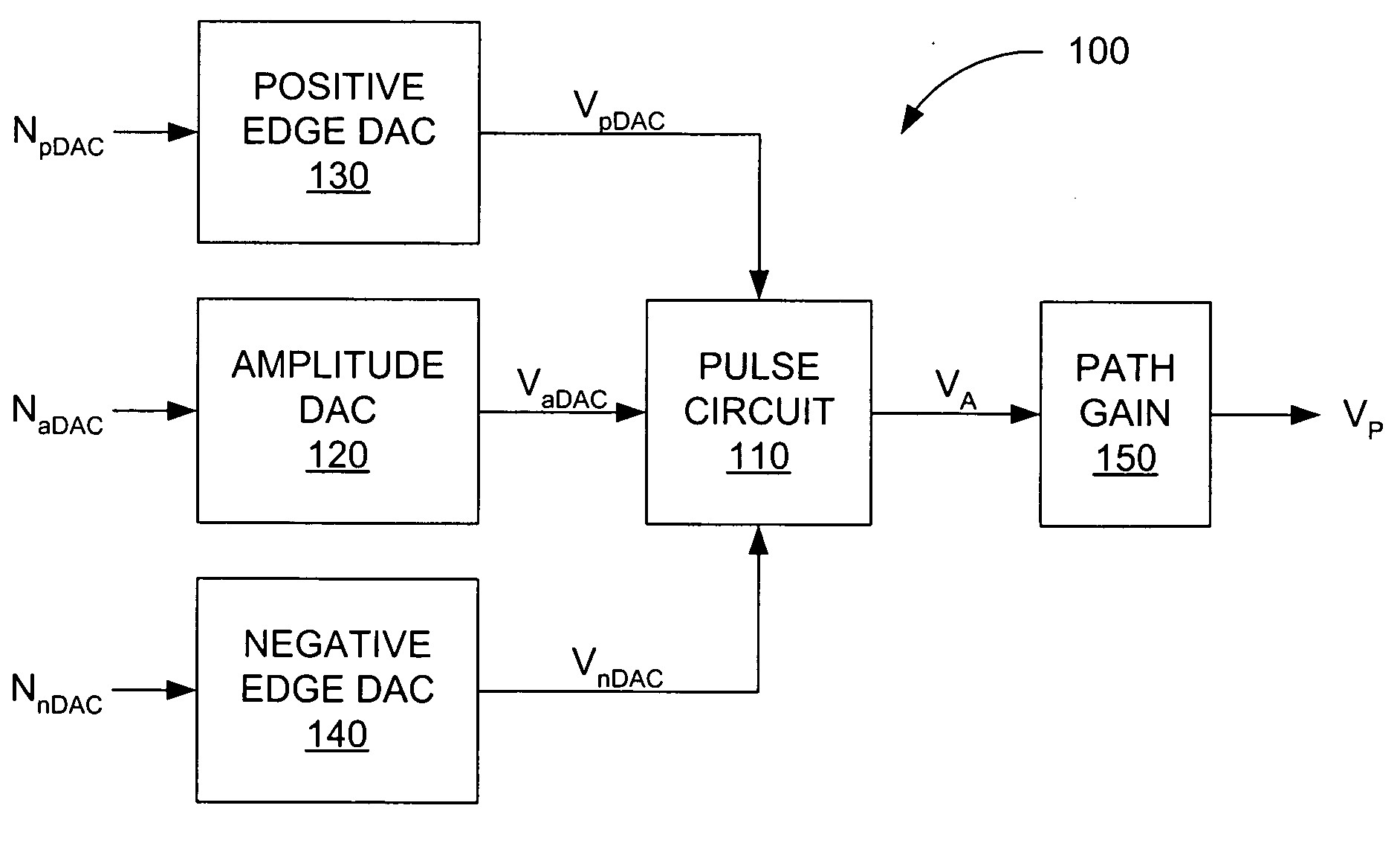
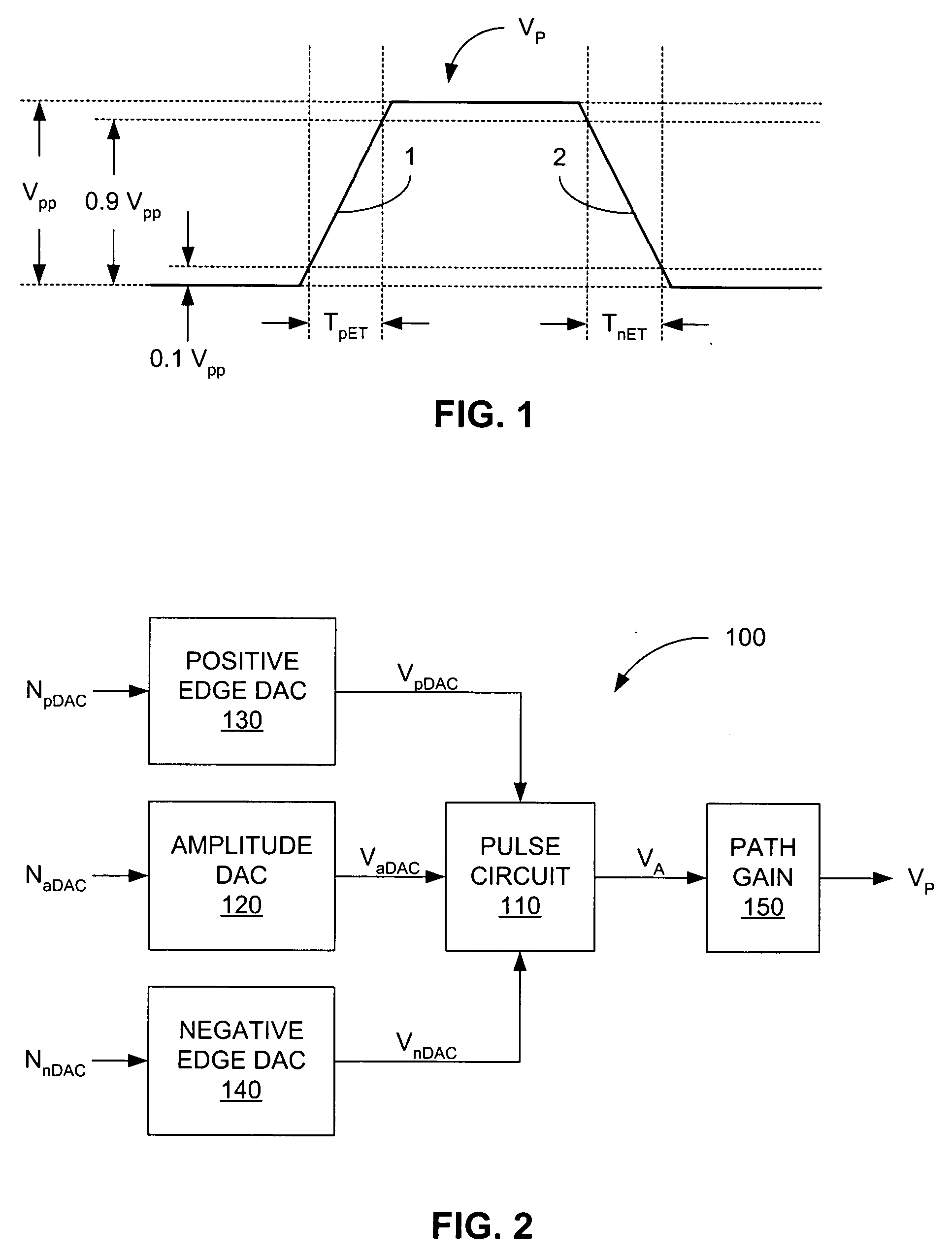
[0012] Before describing the method embodiments of the invention herein disclosed, a block diagram of a portion of a pulse generator 100 upon which the method embodiments may operate is shown in FIG. 1. A pulse circuit 110 is primarily responsible for generating an intermediate pulse waveform VA based on several inputs received. For example, the amplitude of the intermediate pulse waveform VA is determined by an amplitude DAC voltage VaDAC, which is generated by an amplitude DAC 120 and is based on an amplitude DAC number NaDAC. The higher the amplitude DAC number NaDAC, the higher the amplitude of the intermediate pulse waveform VA.

[0013] The pulse circuit 110 also accepts two inputs that allow modification of the slew rate of both the rising and falling edges of the intermediate pulse waveform VA. The slew rate is the rate at which the voltage changes per unit time. The slew rate of the rising edge of that pulse is controlled by a positive edge DAC voltage VpDAC, which is generat...


PUM


Abstract

A method and system for providing variable edge control of pulse waveforms is provided. A positive edge DAC number is set so that the positive edge time of a first pulse waveform of some amplitude is substantially equal to some initial edge time. Similarly, a second positive edge DAC number associated with a second pulse waveform of different amplitude is set so that the positive edge time of the second pulse waveform also equals the initial edge time. Positive gain and offset factors are then generated so that a third positive edge DAC number associated with any pulse waveform may be calculated so that a desired positive edge time of that waveform is produced. Negative edge DAC numbers may be calculated in a similar manner so that the positive and negative edge times of a pulse waveform may be balanced, or more efficient methods may be used.

Description

BACKGROUND OF THE INVENTION [0001] For many years now, one common form of electronics test equipment used by electronics designers has been signal sources. One type of signal source of particular importance is the pulse generator. Typically, pulse generators are designed to produce an electronic pulse signal consisting of a series of one or more pulses, such as a voltage pulse VP shown in FIG. 1. Normally, various parameters describing the pulse signal, such as its amplitude Vpp, positive edge (rise) time TpET associated with a rising edge 1, negative edge (fall) time TnET associated with a falling edge 2, frequency (not denoted), and duty cycle (also not denoted), are selectable by the pulse generator user. Additionally, pulse generators typically operate in several different voltage amplitude ranges, such as zero to 0.1 volts, zero to one volt, zero to ten volts, and so on, with the smaller ranges generally providing greater voltage resolution than larger ranges. [0002] Specifical...

Claims


Application Information

Patent Timeline
Patent Type & Authority Applications(United States)
IPC IPC(8): G06F1/025H03H11/26
CPCG06F1/025
Inventor GAO, FENG
Owner AGILENT TECH INC
Why Eureka
Try Eureka