Label printing apparatus

a label printing and label technology, applied in the field of label printing apparatus, can solve the problems of large multi-function label printing apparatus, increased cost, and inability to transfer printing information

Inactive Publication Date: 2005-07-14
TEAC CORP
View PDF8 Cites 19 Cited by
  • Summary
  • Abstract
  • Description
  • Claims
  • Application Information

AI Technical Summary

Benefits of technology

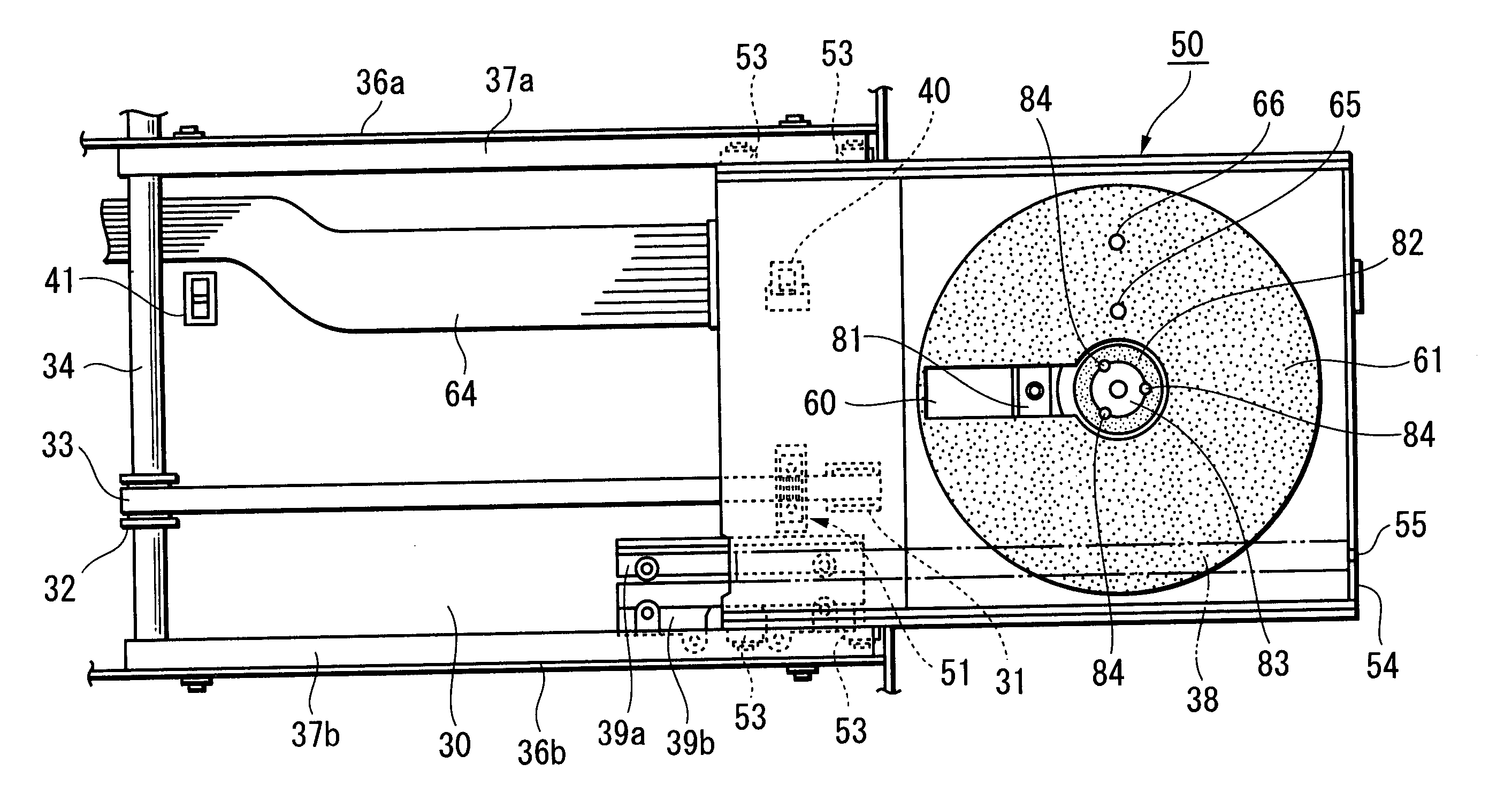
[0022] With the first aspect of the present invention, by internally including, in a disc tray provided in a thermal transfer-type label printer, an information recording / reproduction unit for recording or reproducing information on a recording surface of the optical disc, it becomes possible to additionally use the disc tray as an optical disc apparatus so that it is not necessary to separately provide a dedicated optical disc apparatus for recording and reproducing information on a recording surface of the optical disc and a dedicated label printer for printing information on the label surface of the optical disc and therefore the label printing apparatus can be miniaturized. Also, since a thermal transfer-type device is used as the label printer, printing information can be clearly printed on the label surface of an optical disc without ink dispersing or smudging, so that clear printing information can be printed onto the label surface of the optical disc.
[0024] With the second aspect of the present invention, the clamping of an optical disc by a supporting unit is released when the printing information is printed on the label surface of the optical disc and the recording surface of the optical disc contacts the disc tray, so that when the printing information is printed on the label surface of the optical disc, an appropriate pressure can be applied to the label surface of the optical disc without obstructing the movement of a heat roller that presses a transfer sheet onto the label surface.
[0026] With the third aspect of the present invention, a holding unit, such as a grip sheet or vacuum mechanism, that statically holds the optical disc is provided on the surface of the disc tray, so that when the supporting of the optical disc by the supporting unit is released and the recording surface of the optical disc contacts the disc tray, the optical disc can be held on the disc tray without moving, and when the printing information is printed on the label surface of the optical disc, it is possible to prevent the printed image from becoming displaced on the label surface of the optical disc.
[0028] With the fourth aspect of the present invention, when the disk tray is moved from a position (“loading position”) where the printing information can be printed on the label surface of the optical disc to a position where the optical disc can be changed (“unloading position”), the support unit is moved to the non-supporting position, so that when the disc tray moves to the position where the optical disc can be changed, the clamping of the optical disc will always be released and the center hole of the optical disc will be freed, so that it is possible to have the optical disc automatically changed. In addition, from position information on the disc tray and position information on the supporting unit, it is possible to determine the state of the optical disc on the disc tray.

Problems solved by technology

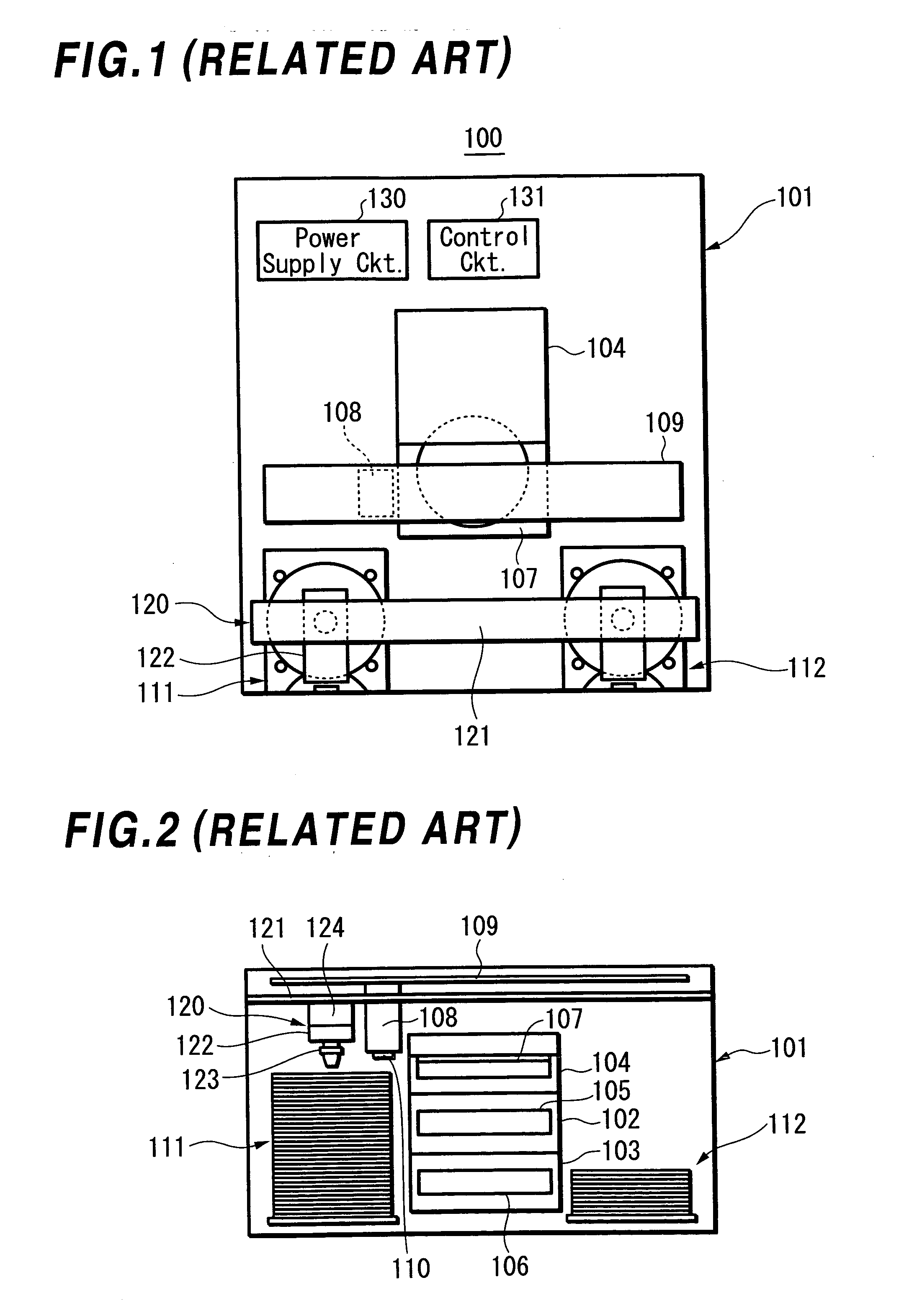
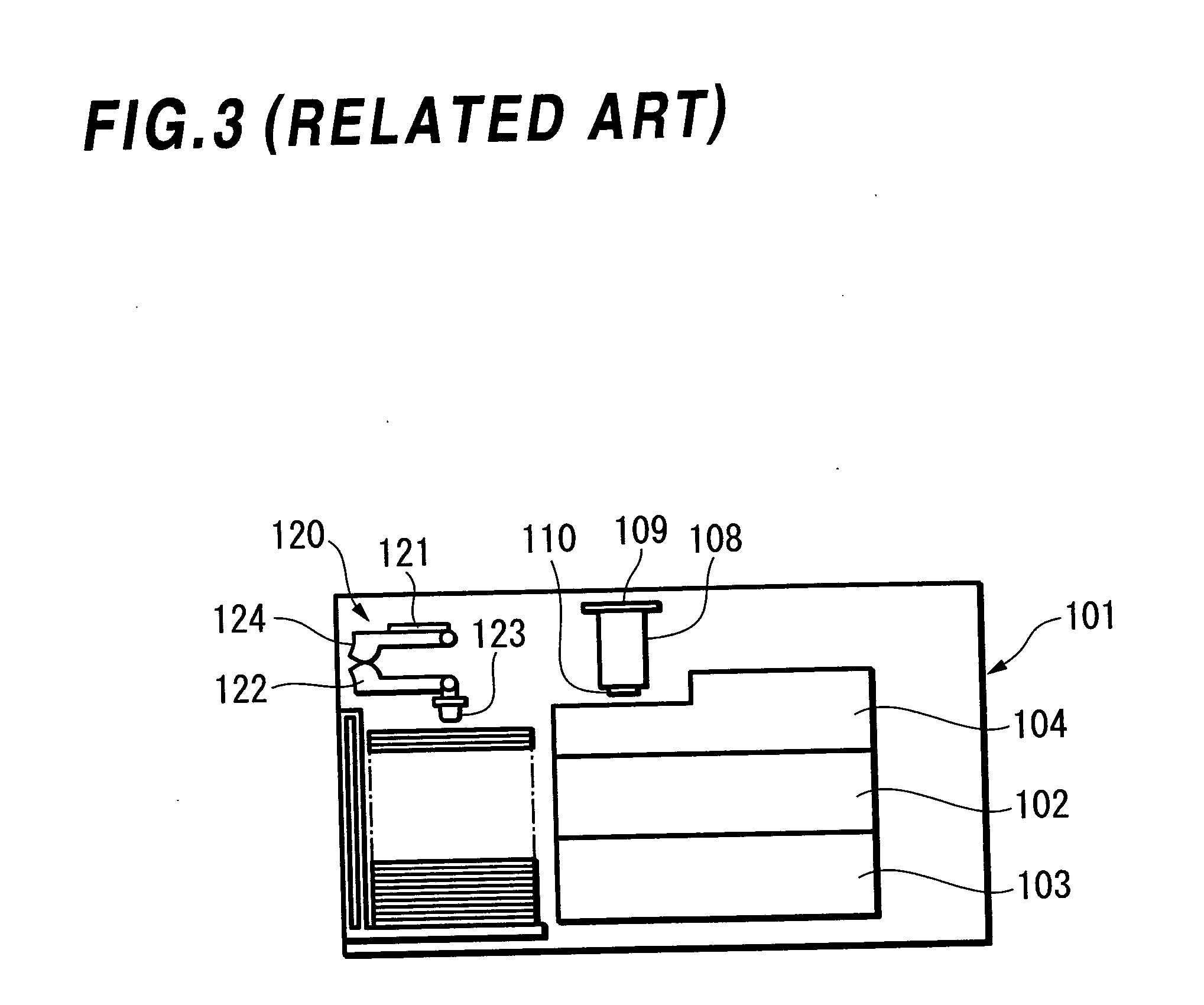
However, although optical disc apparatuses and a label printer are enclosed within the same housing in the multi-function label printing apparatus 100, the optical disc apparatuses and label printer are separate devices, so that there is the problem that the multi-function label printing apparatus is large.
There is also the problem that the optical disc changing process is complex, which leads to increases in cost.
During thermal transfer printing, a heat roller is pressed onto the label surface of an optical disc via a transfer sheet, and if the heat roller is pressed on the optical disc in a state where the optical disc is placed on a turntable, that is, in a state where the optical disc has been lifted up from the disc tray, the optical disc will warp, so that it will not be able to transfer the printing information and there is even the risk of the optical disc becoming damaged.
However, ink jet printers print by spraying ink onto the label surface of an optical disc, so that if the optical disc is rotated before the sprayed ink has dried, due to centrifugal force the ink on the optical disc can disperse towards the outer periphery of the optical disc or become blurred, so that there is the problem of poor image quality for the printed image.
In addition, with apparatuses such as those disclosed in Patent Documents 1 to 4 where the optical disc is rotated and printing is carried out in synchronization with the rotation of the optical disc, there is the problem that ink sprayed from the head is dispersed by wind pressure produced between the label surface of the optical disc and the head, which lowers the quality of the printed image and means that the desired printing information cannot be printed properly.

Method used


Image

  • Label printing apparatus
  • Label printing apparatus
  • Label printing apparatus

Examples


Embodiment Construction

[0052] An embodiment of the present invention will now be described with reference to FIG. 4 to FIG. 19.

[0053]FIG. 4 and FIG. 5 are schematic diagrams showing a label printer according to the present invention. FIG. 4 is a perspective view of the label printer, and FIG. 5 is a side elevation. The label printer 1 is broadly divided into a head unit 2, a guide unit 3, a transfer roller unit 4, a disc conveying unit 5, an ink ribbon cassette 6, and a thermal transfer film ribbon cassette 7. The ink ribbon cassette 6 and the thermal transfer film ribbon cassette 7 can be attached to and detached from the label printer 1 from the side, with the ink ribbon cassette 6 being set on the label printer 1 so that a printing surface 8a of an ink ribbon 8 is positioned between the head unit 2 and the guide unit 3 and the thermal transfer film ribbon cassette 7 being set so that a thermal transfer film ribbon 9 used as a transfer sheet is wound around the transfer roller unit 4.

[0054] The ink ri...


PUM

PropertyMeasurementUnit
speedaaaaaaaaaa
poweraaaaaaaaaa
rotationaaaaaaaaaa

Abstract

A thermal transfer-type label printer and an optical disc apparatus are integrated to miniaturize a multi-function label printing apparatus. An information recording / reproducing unit that carries out recording or reproduction of information on a recording surface of an optical disc is incorporated within a disc tray unit of a label printing apparatus that presses a thermal transfer film ribbon, on which printing information has been formed, onto a label surface of an optical disc mounted on a disc mounting part of the disc tray unit, and transfers the printing information onto the label surface using a heat roller. The recording or reproduction of information on the recording surface of the optical disc and the transferring of the printing information on the label surface of the optical disc are carried out on the disc tray unit. When transferring the printing information, the clamping of the optical disc by a disc clamper is released and a turntable and the disc clamper are withdrawn to a non-clamping position.

Description

BACKGROUND OF THE INVENTION [0001] 1. Field of the Invention [0002] The present invention relates to a label printing apparatus that records or reproduces information on an optical disc such as a CD (Compact Disc) or DVD (Digital Versatile Disc) and also prints information on a label surface of the optical disc. [0003] 2. Description of the Related Art [0004] In recent years, the spread of optical discs such as CD-R / RW and DVD-R / RW / RAM has been accompanied with increasing demand for a label printer that can print images and / or character information, which has been generated on a personal computer or the like, on the label surface (upper surface) of a user-made CD or DVD. Also, multi-function label printing apparatuses, where an optical disc apparatus that records information on an optical disc and the label printer mentioned above are combined and enclosed within a single housing, have also entered the market. [0005] As shown in FIG. 1 to FIG. 3, in one example of a multi-function l...

Claims


Application Information

Patent Timeline
Patent Type & Authority Applications(United States)
IPC IPC(8): B41J2/325B41J2/47B41J13/10B41J3/407G11B17/028G11B17/08G11B23/00G11B23/40
CPCB41J3/4071B41J3/4075G11B23/40G11B17/08G11B23/00G11B17/028
Inventor SUKIGARA, MOTOYUKISHIAKU, TATSUO
Owner TEAC CORP
Why Eureka
Try Eureka