Method for MPLS link protection

a multi-protocol label switching and link protection technology, applied in data switching networks, frequency-division multiplexes, instruments, etc., can solve the problems of insufficient backup lsp, insufficient bandwidth utilization optimization, and very busy paths, so as to achieve short service interruption time, high bandwidth utilization, and low overhead

a multi-protocol label switching and link protection technology, applied in data switching networks, frequency-division multiplexes, instruments, etc., can solve the problems of insufficient backup lsp, insufficient bandwidth utilization optimization, and very busy paths, so as to achieve short service interruption time, high bandwidth utilization, and low overhead

US20050152269A1Inactive Publication Date: 2005-07-14IND TECH RES INST

Image

  • Method for MPLS link protection
  • Method for MPLS link protection
  • Method for MPLS link protection

Examples


Embodiment Construction

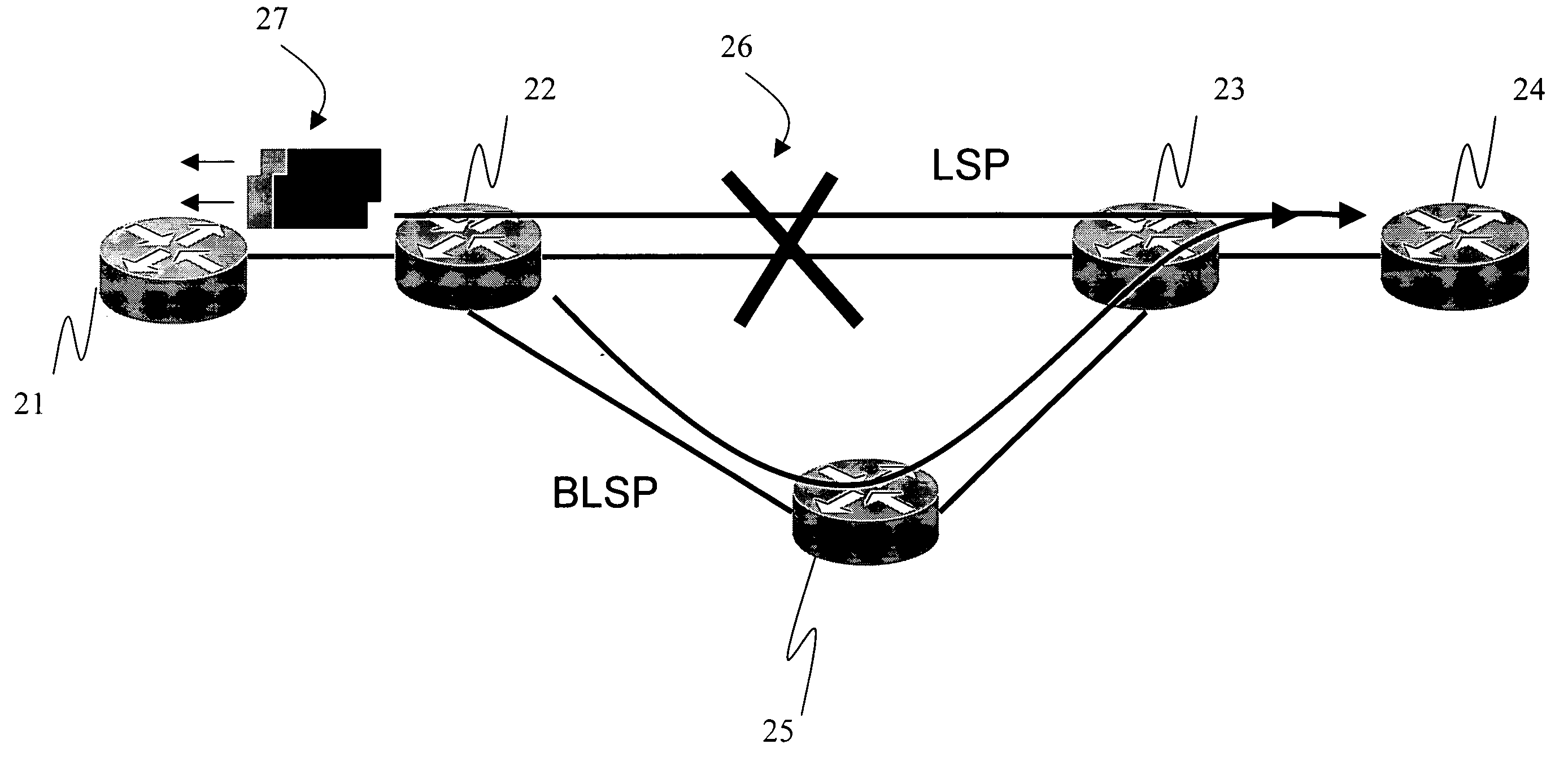
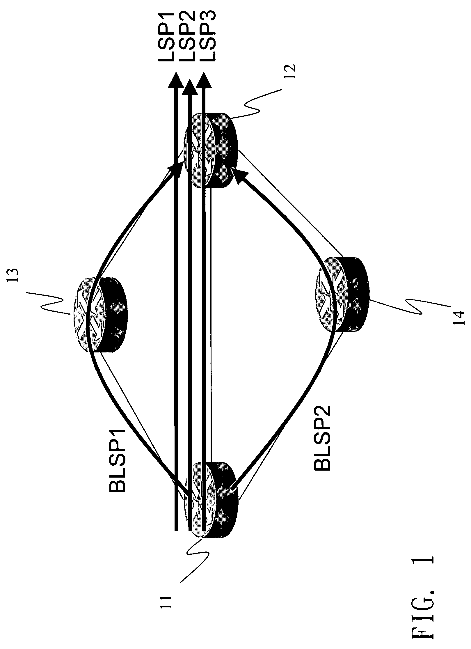
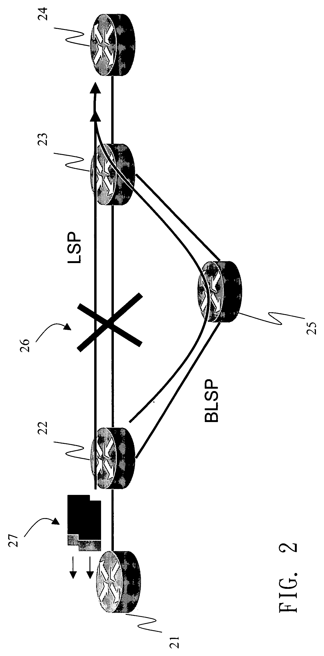
[0016] With reference to FIG. 1, the disclosed method for multi-protocol label switching (MPLS) link protection first builds several backup label switching paths (LSP) among label switching routers 11, 12, 13, 14. In order to prevent several LSP's from sharing the same backup LSP and resulting in congestion on that LSP, a parameter MaxB.W is defined to indicate the maximum bandwidth that can be transmitted over each LSP. This parameter is mainly determined by the transmission capacity of the LSP and that of the backup LSP. For example, suppose MaxB.W=5MB and the quality of service bandwidth parameters of three LSP's LSP1, LSP2 and LSP3 are 3MB, 2MB, and 1MB, respectively. Then one has to establish two backup LSP's, as BLSP1 (11-13-12) and BLSP2(11-14-12) in the drawing. The backup LSP BLSP1 is used to protect the LSP's LSP1 and LSP2 (3M+2M=5M). The other backup LSP BLSP2 is used to protect LSP3. When the backup LSP's are not enough, the network device should send out a warning messa...


PUM


Abstract

A method for MPLS link protection pre-builds backup LSP. When the LSP breaks down, it can redirect the LSP to the backup LSP within the minimal time and rearrange an auxiliary LSP after breaking down for a default time. By the guiding and the rearrangement, the method prevents the service of the MPLS from being unavailable when the MPLS breaks down and optimizes the utilization of the MPLS resources.

Description

BACKGROUND OF THE INVENTION [0001] 1. Field of Invention [0002] The invention relates to a multi-protocol label switching (MPLS) link protection method and, in particular, to a MPLS link protection method that utilizes both pre-built and post-built backup LSP's. [0003] 2. Related Art [0004] The main difference between a multi-protocol label switching (MPLS) network and a common IP network is in that the data transmission path of the IP network is determined by a routing table. Unless the routing table is modified, it may happen that some paths are very busy at a particular time while others are basically idle. The MPLS network uses the label to determine the routing path of a packet. Therefore, it has the function of traffic engineering. The transmission path can be controlled by modifying the packet label. It is thus very flexible in practice. [0005] An MPLS network usually has tens of thousands of label switching paths (LSP's). This means that there are over hundreds of LSP's on a...

Claims


Application Information

Patent Timeline
14 Jul 2005
Publication
US20050152269A1
IPC
G06F11/00; G08C15/00; H04L12/28; H04L12/56
CPC
H04L45/00; H04L45/50; H04L45/28; H04L45/22
Inventors
LIU, REN-HAO