
Systems and methods for compartmental replacement in a knee

a compartmental replacement and knee technology, applied in the field of human body joints, can solve the problems of substantial trauma, the device of the '855 patent suffers from several limitations, and the bone resection required for mounting the components may require extensive recovery time,

Active Publication Date: 2005-07-14
DEPUY PROD INC
View PDF99 Cites 222 Cited by
  • Summary
  • Abstract
  • Description
  • Claims
  • Application Information

AI Technical Summary

Benefits of technology

[0024] The above-described features and advantages, as well as others, will become more readily apparent to th

Problems solved by technology

The femoral component replaces the lateral condyle, medial condyle, and patellofemoral portions of the femur because one or more of these areas of the knee are diseased and are no longer wearing well or providing an adequate range of motion for a patient.
While providing a number of benefits, the device of the '855 patent suffers from several limitations.
The preparation of a subject for TKR surgery usually causes substantial trauma.
A large incision is required for insertion of all of the components of a TKR system and the bone resection required for mounting of the components may require extensive recovery time.
Thus, single piece replacement components such as the device of the '855 patent require a large incision.
Such methods are subject to problems as the replacement component is subjected to various stresses and impacts.
One such problem is the eventual loosening of the components.
When one component loosens, adjacent components may rub together, generating frictional debris and premature failure of the components..
Yet another limitation of implant systems is that as a commercial consideration, many replacement components are mass-produced.
While beneficially lowering the cost of implants, these systems are generally provided in a limited number of discrete sizes that most likely will not be precisely the size needed for a patient.

Method used


Image

  • Systems and methods for compartmental replacement in a knee
  • Systems and methods for compartmental replacement in a knee
  • Systems and methods for compartmental replacement in a knee

Examples


Embodiment Construction

Individual Components

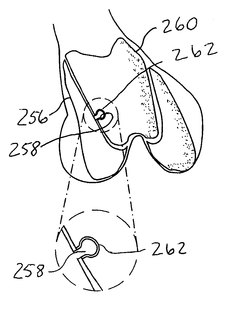
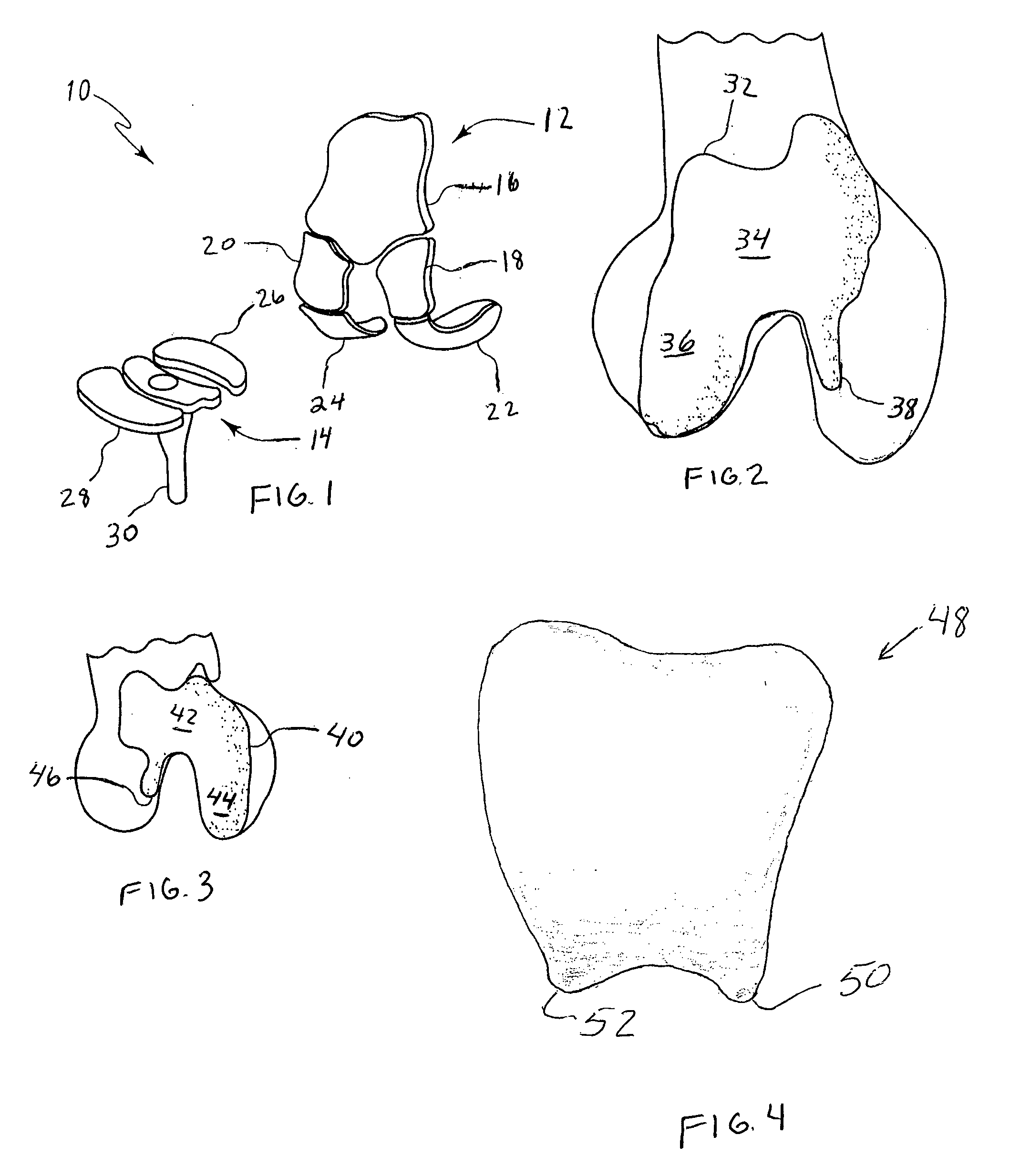
[0115]FIG. 1 shows one embodiment of a system 10 made in accordance with the principles of the present invention. The system 10 is comprised of a femoral replacement 12, a tibial replacement 14, and a patellar replacement (not shown). The femoral replacement 12 includes a patellofemoral joint (PFJ) component 16, an upper lateral condyle component 18, an upper medial condyle component 20, a lateral femoral anterior / posterior condyle component 22, and a medial femoral anterior / posterior condyle component 24. In accordance with one embodiment (not shown) the upper condyle components and femoral anterior / posterior condyle components are provided as a single component. The tibial replacement 14 includes a medial meniscus component 26, a lateral meniscus component 28, and a tibial stem component 30.

[0116] By segmenting the replacements into upper and anterior-posterior medial, and lateral, PFJ, meniscus and tibial stem components, the system 10 of the present inven...


PUM


Abstract

A knee replacement system provides a knee implant that may be used to more accurately replicate the diameter of a natural knee. In one embodiment, a patellofemoral component is connected to the posterior portion of a condylar component by screws that pass through the femur allowing the patellofemoral component and the condylar component to be torqued against opposing sides of the femur. Two additional screws are used to connect the patellofemoral component to an anterior portion of the condylar component. A gap may be left between the patellofemoral component and the anterior portion of the condylar component if needed to provide precise replication of the diameter of the natural knee from the patellofemoral component to the condylar component.

Description

[0001] This application claims priority to U.S. provisional application No. 60 / 535,967 filed Jan. 12, 2004.FIELD OF THE INVENTION [0002] This invention relates generally to prosthesis for human body joints, and, more particularly, to prosthesis for knees. BACKGROUND OF THE INVENTION [0003] Total knee replacement (TKR) surgery and component systems for replacing compartments of a knee in total replacement surgery are well-known. Typically, the surgery involves resecting the distal end of a femur so a femoral component may be mounted to the femur. The femoral component replaces the lateral condyle, medial condyle, and patellofemoral portions of the femur because one or more of these areas of the knee are diseased and are no longer wearing well or providing an adequate range of motion for a patient. [0004] In TKR surgery, the proximal end of the tibia is also resected so that a tibial component may be mounted to the tibia to receive the lateral and medial condyles of the femoral compon...

Claims


Application Information

Patent Timeline
IPC IPC(8): A61B17/14A61B17/15A61B17/17A61F2/00A61F2/30A61F2/38A61F2/46
CPCA61B17/14A61B2017/1778A61B17/1764A61F2/38A61F2/3877A61F2002/30433A61F2002/30604A61F2002/30975A61F2002/3895A61F2002/4632A61F2220/0041A61B17/1739A61B2017/143A61B2017/145A61B17/155A61B17/149A61B17/1778
Inventor ARAM, LUKEAUGER, DANIEL D.HAYDEN, ADAM I.LEE, JORDAN S.
Owner DEPUY PROD INC
Learn More