Method, device and program for managing volume
a volume management and program technology, applied in the field of volume management, can solve the problems of no disclosure of the volume migration among the multiple storage subsystems, difficult for the administrator to use the hints as a way to allocate the volume, and significant problems, and achieve the effect of effective utilization of resources
- Summary
- Abstract
- Description
- Claims
- Application Information
AI Technical Summary
Benefits of technology
Problems solved by technology
Method used
Image
Examples
embodiment 1
(1) System Structure
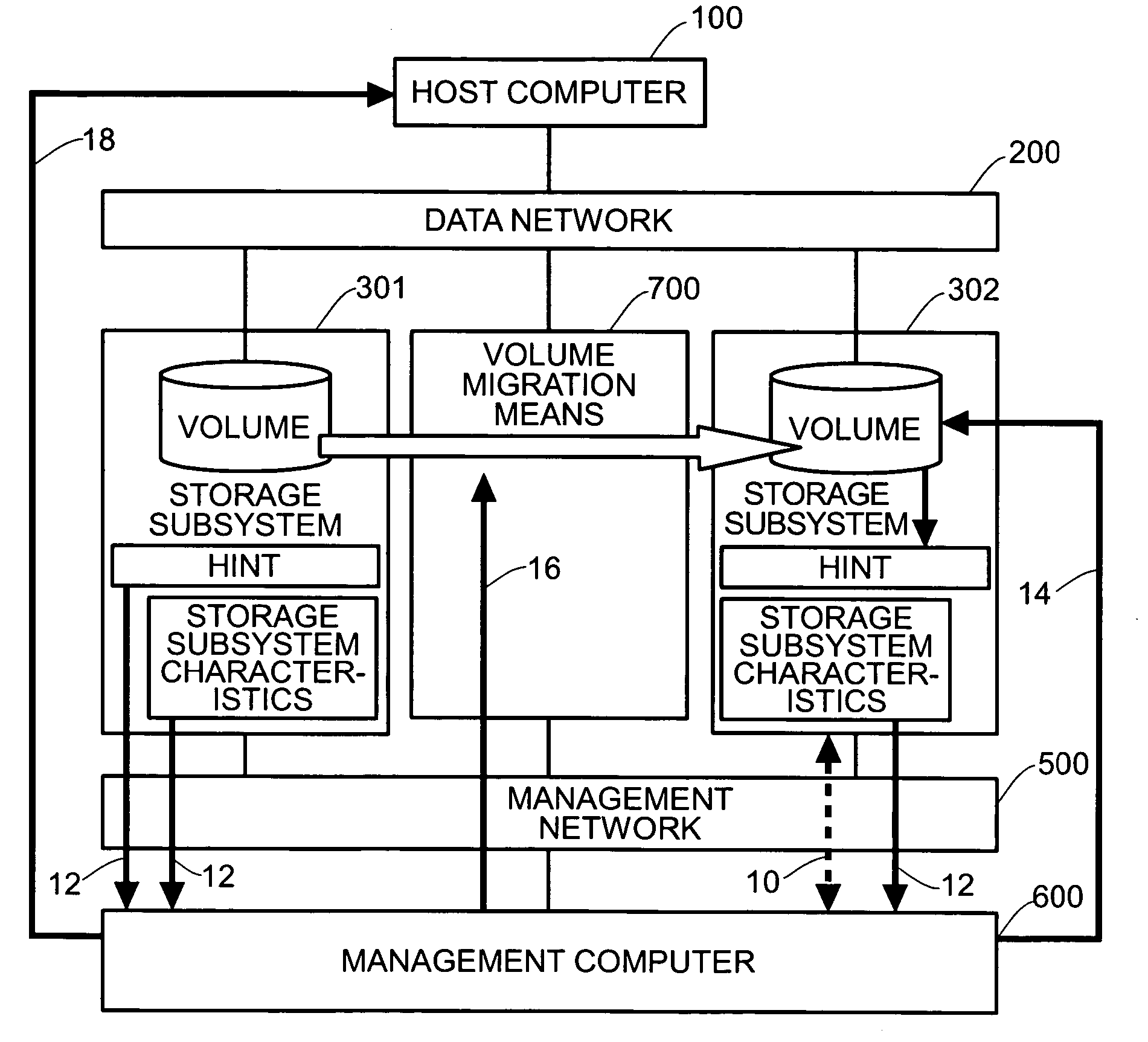
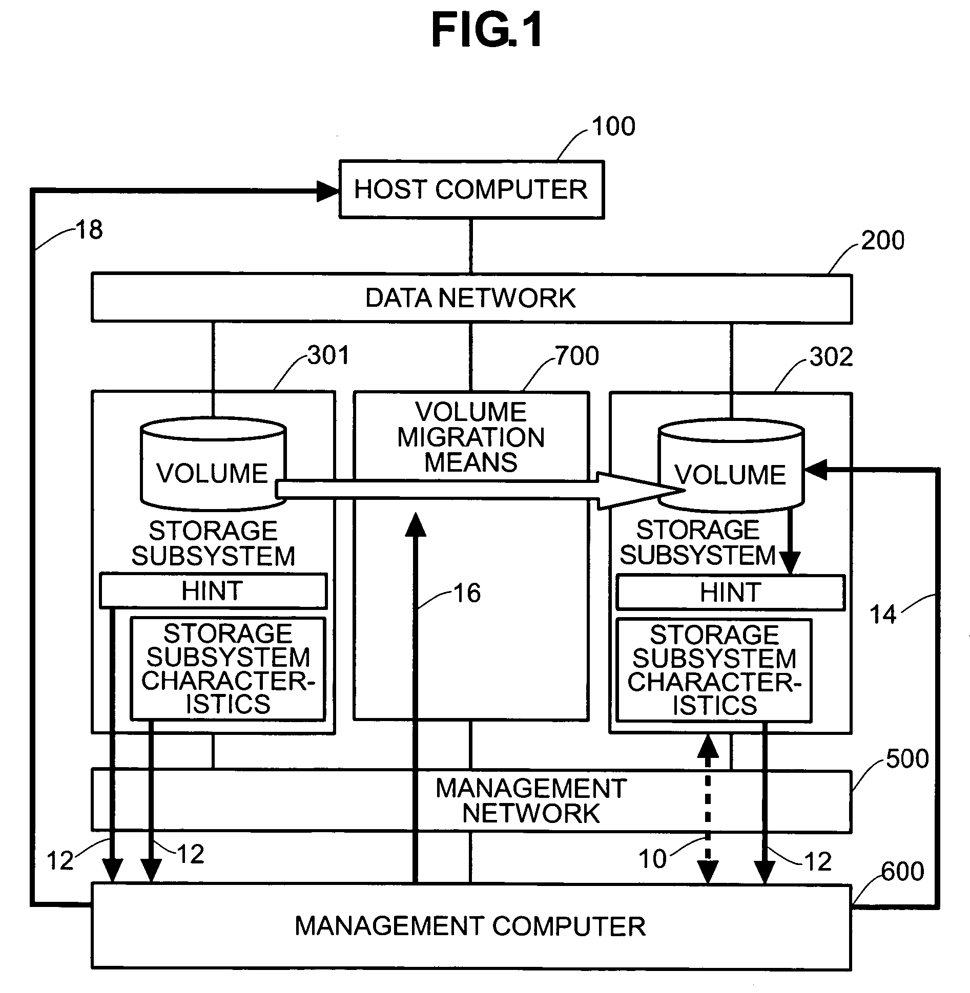
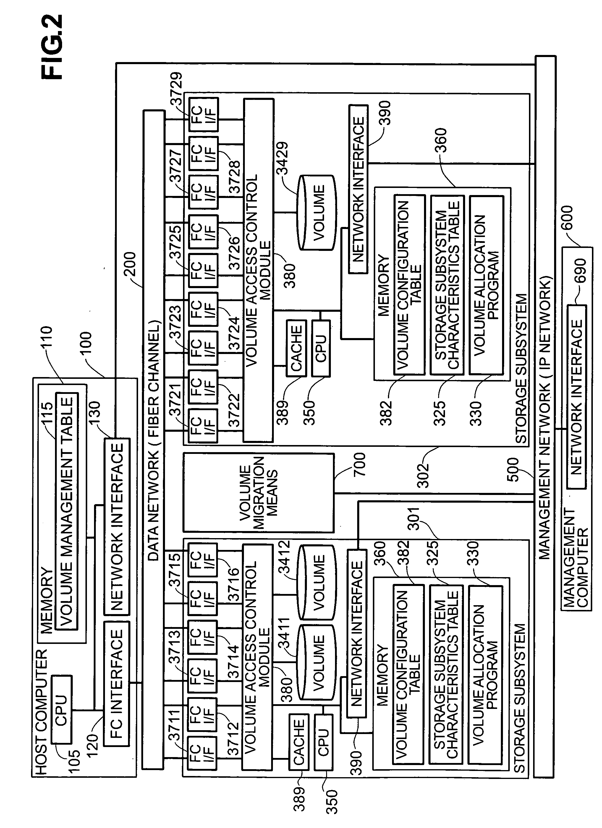
[0039]FIG. 2 shows a system structure in accordance with Embodiment 1. In the computer system shown in FIG. 2, the host computer 100, which uses the volume, is connected to the storage subsystem 301 and the storage subsystem 302 through the data network 200; and the management computer 600, which manages the storage subsystem 301 and the storage subsystem 302, is connected to the storage subsystem 301 and the storage subsystem 302 through the management network 500. In the system shown in FIG. 2, the computer system (which is constituted of the host computer 100, the storage subsystem 301 and the management computer 600) has the storage subsystem 302 added to it. (This is a variant construction.) Furthermore, the data network 200 is provided with the volume migration means 700 for transferring data among the volumes. The volume migration means 700 is connected to the management network 500 so that it can receive data transfer requests from the management comput...
embodiment 2
(1) System Structure
[0122]FIG. 9 shows a system structure in accordance with Embodiment 2. Embodiment 2 will be explained with respect to a case where a storage subsystem 303 is added to the computer system having the storage subsystem 301.
[0123] The differences between the present embodiment and Embodiment 1 will be explained below.
[0124] A first difference is that, when the storage subsystem 303 is added in the present embodiment, the storage subsystem 301 is removed from the data network 200 and connected to the storage subsystem 303.
[0125] A second difference is that, in Embodiment 1, the volume migration means 700 was connected to the data network 200, but in the present embodiment the volume migration means 700 is provided within the storage subsystem 303.
[0126] A third difference concerns the structure of the management computer 600 shown in FIG. 12. The construction in the present embodiment uses the structure from Embodiment 1, but also includes a volume access switch...
example 1
Concrete Example 1 of Reevaluation and Transfer of Volume in Present Embodiment
[0172] The management computer 600 starts the reevaluation of the volume 3412, which is in the first line of the volume information 385 (step 16020).
[0173] First, the management computer 600 references the value of the hint information AccessBandwidthHint for the volume 3412. The value of the AccessBandwidthHint is “10”.
[0174] Then, when the management computer 600 finds that “10” is the value defined for the AccessBandwidthHint of the storage subsystem 326 and the storage subsystem 327 from the storage subsystem 301 and the storage subsystem 303, it is clear that the storage subsystem 301 has a bandwidth of 2 Gbps, but the storage subsystem 303 has an accelerated bandwidth of 10 Gbps (step 16060).
[0175] Therefore, for the volume 3412 in the storage subsystem 301, instead of providing the external volume to the host as the external storage subsystem via the storage subsystem 303, the volume itself can ...
PUM
 Abstract
Description
Claims
Application Information
 - R&D
- Intellectual Property
- Life Sciences
- Materials
- Tech Scout
- Unparalleled Data Quality
- Higher Quality Content
- 60% Fewer Hallucinations
Browse by: Latest US Patents, China's latest patents, Technical Efficacy Thesaurus, Application Domain, Technology Topic, Popular Technical Reports.
© 2025 PatSnap. All rights reserved.Legal|Privacy policy|Modern Slavery Act Transparency Statement|Sitemap|About US| Contact US: help@patsnap.com


