Expansion joint holder and a method of pouring concrete sections

a technology of expansion joint and concrete section, which is applied in the direction of bridges, roads, constructions, etc., can solve the problems of large area concrete slabs that are prone to cracks, joints that can easily float, time-consuming and inefficient processes, etc., and achieve the effect of more efficient pouring of concr

Inactive Publication Date: 2005-07-21
WOJTASZEK CASIMIR J
View PDF28 Cites 3 Cited by
  • Summary
  • Abstract
  • Description
  • Claims
  • Application Information

AI Technical Summary

Benefits of technology

[0016] The present invention overcomes the disadvantages of prior art concrete expansion joints by providing a concrete section expansion joint holder that holds an expansion joint such that the resulting joint is substantially straight, wherein the holder does not need to be removed either during or after the pouring of the concrete, thereby allowing more efficient pouring of concrete over large layout surfaces.

Problems solved by technology

In the absence of being divided in this manner into smaller concrete areas, a large area concrete slab is prone to crack due to thermal expansion and contraction and ground settling.
Also, these joints can easily float when the liquid concrete is poured into the form.
This is a time consuming and inefficient process.
This water may freeze, expand and injure the slabs.
Working up of asphalt joints creates voids in the space between the slabs where water can collect, freeze and injure the slabs.
Since it is impractical to pour concrete a section at a time, it is necessary to pour a large amount of coverage at one time and then work the concrete as it begins to harden.
This method is problematic because it is time-consuming, laborious and does not assure straight, vertical expansion joints since the rubber strip can move around once one or both of the support boards is removed.
The problem therefore is to position expansion joints between adjacent portions of concrete which are straight and require less time and effort to make so as to increase efficiency in pouring adjacent concrete portions, such as in sidewalks and driveways.

Method used


Image

  • Expansion joint holder and a method of pouring concrete sections
  • Expansion joint holder and a method of pouring concrete sections
  • Expansion joint holder and a method of pouring concrete sections

Examples


Embodiment Construction

[0026] The phrase “resulting joint is substantially straight” as used herein means the expansion joint is linear and not wavy or curved.

[0027] The phrase “substantially parallel” as used herein means planes which are less than about 10 degrees, preferably less than about 5 degrees and more preferably less than about 2 degrees off of parallel.

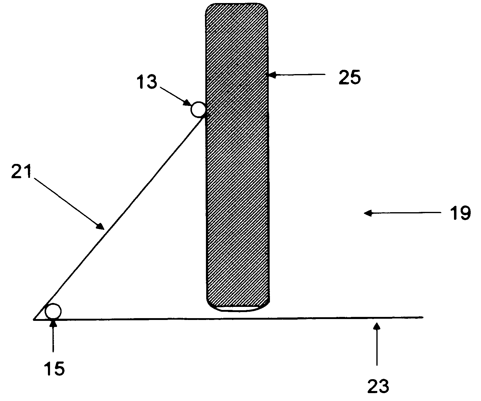
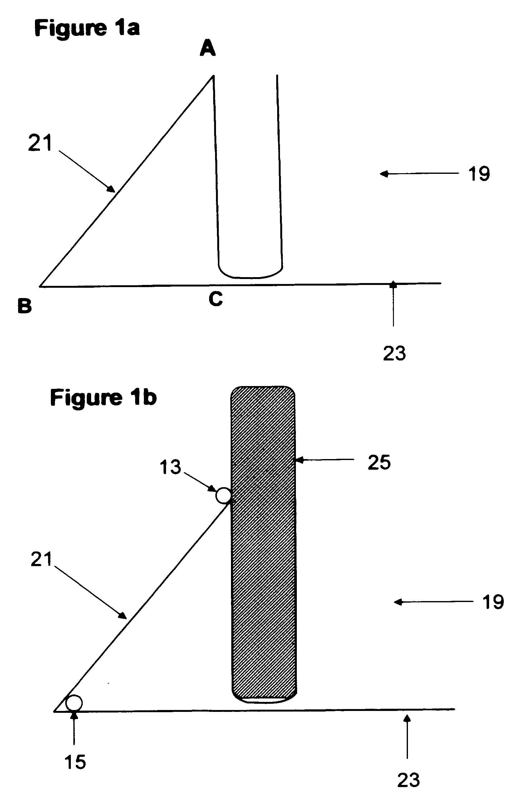
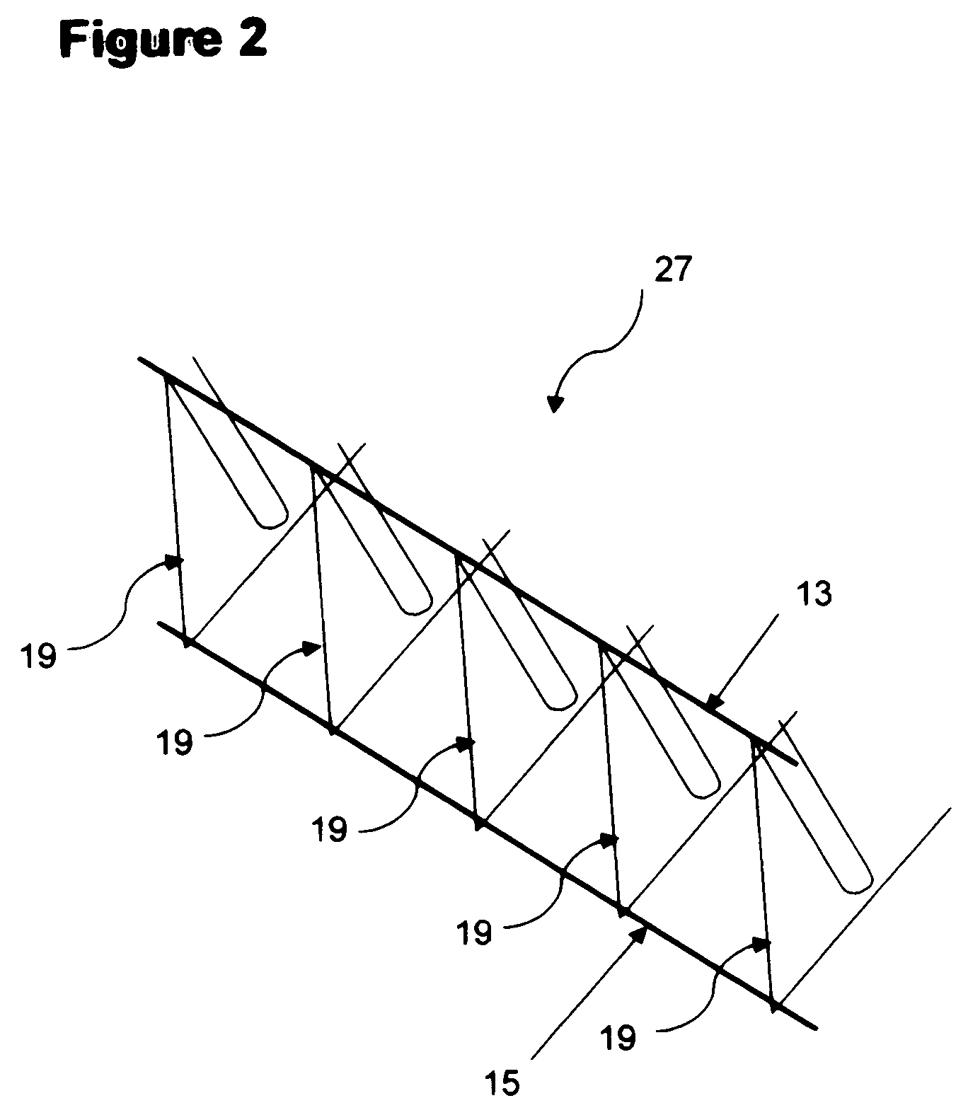
[0028]FIG. 1a shows a support component 19 which is integral to the instant invention.

[0029] Each shaped support component 19 comprises two legs (21 and 23) angled at an acute angle with respect to each other and continuous with each other. The two legs are continuous with and in the same plane as a substantially U-shape that serves as a slot for insertion of an expansion joint. One side of the U-shape forms one side of substantially a right triangle having vertexes A, B and C wherein leg 21 connects vertices A and B and part of leg 23 connects vertices B and C. This right triangle is in the same plane as the U-shape. The bottom of the U-shap...


PUM

PropertyMeasurementUnit
diameteraaaaaaaaaa
diameteraaaaaaaaaa
thickaaaaaaaaaa

Abstract

The invention provides a concrete section expansion joint holder that holds an expansion joint such that the resulting joint is straight, wherein the holder does not need to be removed either during or after the pouring of the concrete, thereby allowing more efficient pouring of concrete over large layout surfaces. Also provided is method of pouring concrete using the expansion joint holder. The present invention is used in the construction industry to create concrete sidewalks and roads.

Description

FIELD OF THE INVENTION [0001] The present invention relates to construction and building materials and methods and more particularly, to a concrete section expansion joint holder enabling the positioning and holding of an expansion joint rubber strip to produce straight expansion joints with less effort and time. BACKGROUND OF THE INVENTION [0002] Concrete expansion joints are an essential component in the proper construction of many large concrete surfaces, such as floors, roofs, parking lots, roads, airport runways and the like. These joints enable expansion and contraction of the concrete or mortar surfaces based on surrounding temperatures, which reach hot and cold extremes, respectively, in summer and winter periods, and other factors including shifting of soil underneath the slabs. These joints are meant to eliminate the deterioration of the slab due to random cracks which otherwise form in the concrete. [0003] As used herein the term “joints” applies equally to expansion and ...

Claims


Application Information

Patent Timeline
Patent Type & Authority Applications(United States)
IPC IPC(8): E01C11/12
CPCE01C11/126
Inventor WOJTASZEK, CASIMIR J.
Owner WOJTASZEK CASIMIR J
Why Eureka
Try Eureka