Sheet-fed offset rotary printing press

Inactive Publication Date: 2005-07-21
KOMORI CORP
View PDF16 Cites 15 Cited by
  • Summary
  • Abstract
  • Description
  • Claims
  • Application Information

AI Technical Summary

Benefits of technology

[0005] It is an object of the present invention to provide a sheet-fe

Problems solved by technology

Then, not only the printing quality decreases, but also extra time is required for adjustment to correct the misregister, decreasing the productivity.
If ink from an inking unit un

Method used


Image

  • Sheet-fed offset rotary printing press
  • Sheet-fed offset rotary printing press
  • Sheet-fed offset rotary printing press

Examples


first embodiment

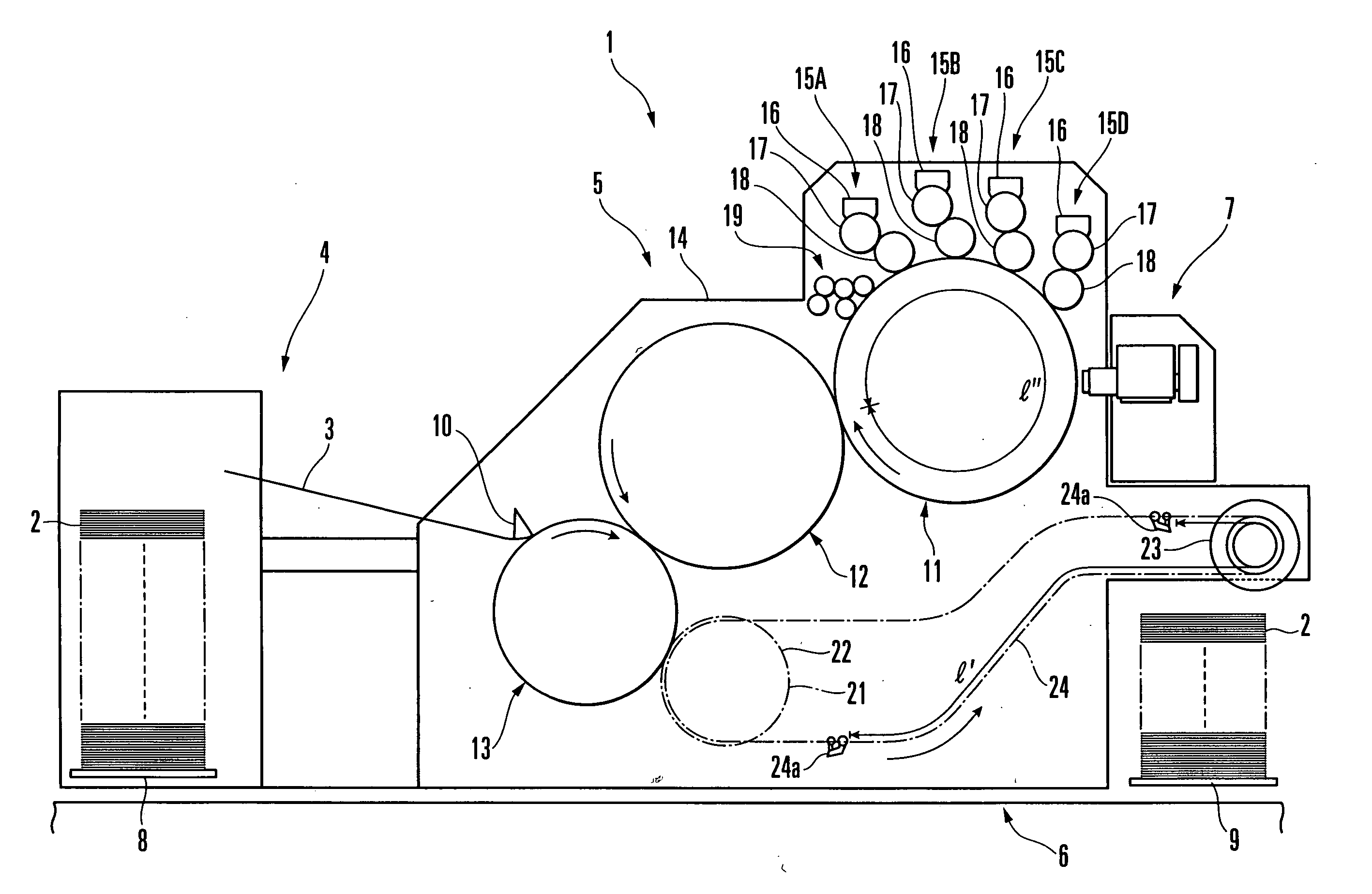
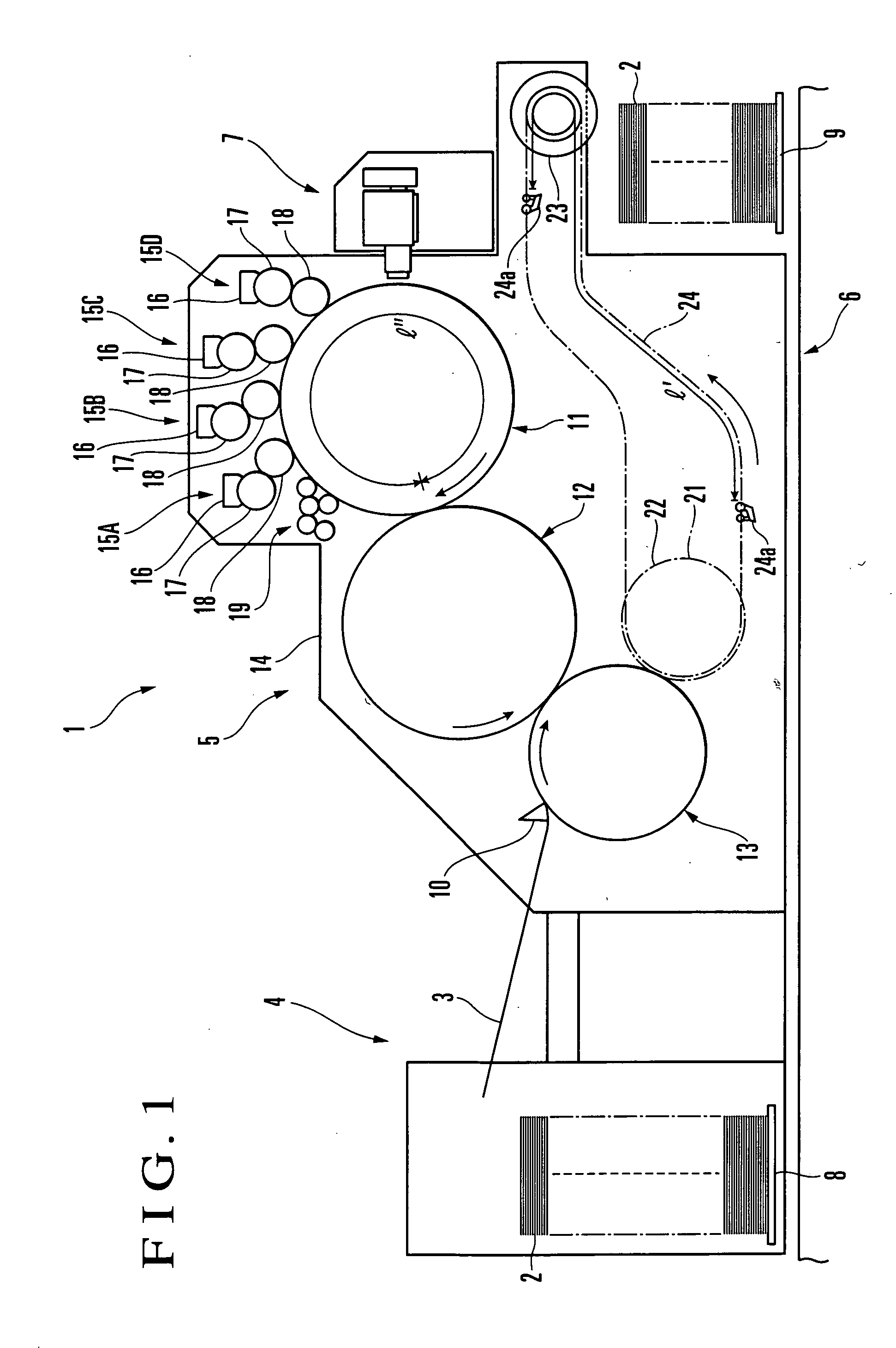
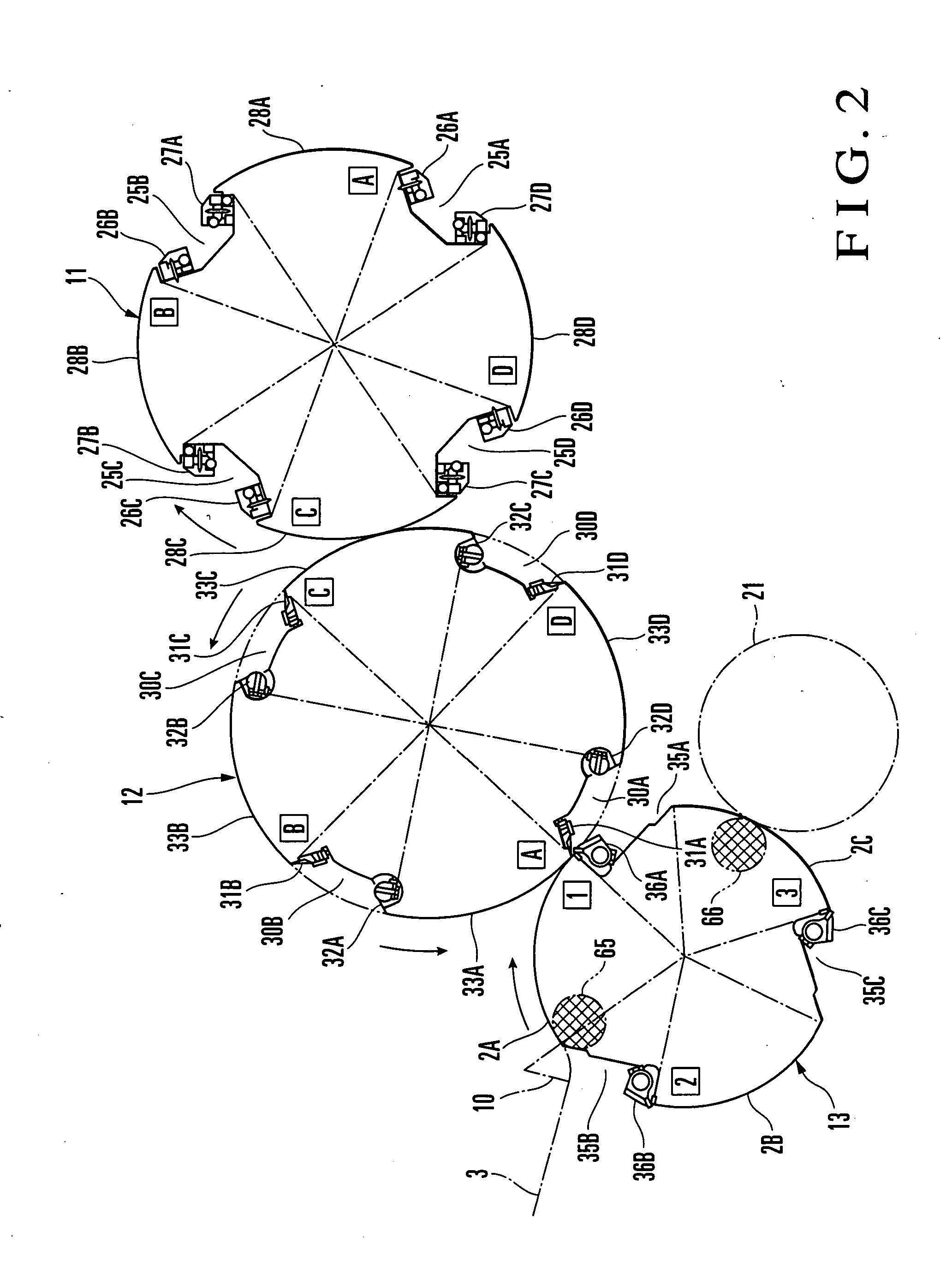
[0018] A sheet-fed offset rotary printing press according to the present invention will be described with reference to FIGS. 1 to 5B.

[0019] Referring to FIG. 1, a sheet-fed offset rotary printing press 1 includes a feeder 4 which feeds paper sheet 2 stacked on a pile board 8 onto a feeder board 3 one by one, a printing unit 5 which prints the fed paper sheet 2, a delivery unit 6 which conveys the printed paper sheet 2 and delivers it onto a pile board 9 to stack it there, and a plate making device 7 which plate-makes a plate mounted on the outer surface of a plate cylinder 11 that forms the printing unit 5. The paper sheet 2 fed onto the feeder board 3 is positioned by a registration device (not shown) and gripped by the grippers of a swing arm shaft gripper 10. After that, the paper sheet 2 is conveyed to the outer surface of an impression cylinder 13 that forms the printing unit 5, and gripping-changed to gripper devices 36A to 36C of the impression cylinder 13 by a gripper openin...

second embodiment

[0138]FIG. 10 is a model view showing an impression cylinder for a sheet-fed offset rotary printing press according to the present invention.

[0139] The second embodiment is different from the first embodiment in that an impression cylinder 13 has a quintuple size, that five gripper devices are provided to the impression cylinder 13, and that five printing surfaces are formed on the outer surface of the impression cylinder 13. In this structure, the blanket cylinder 12 is thrown on onto and off from the impression cylinder 13 by a cylinder throw-on / throw-off device 39 at appropriate timings in the same manner as with the impression cylinder having three printing surfaces described above. Thus, multicolor printing can be performed on five paper sheets gripped by the five gripper devices of the impression cylinder 13.

[0140] In the embodiments described above, the printing cylinder includes the plate cylinder 11 and the blanket cylinder 12 which is in contact with the plate cylinder 11...


PUM


Abstract

A sheet-fed offset rotary printing press includes one plate cylinder, one blanket cylinder with the same size as that of the plate cylinder, one impression cylinder, one plate making device, four inking devices, four roller throw-on/throw-off devices, and a cylinder throw-on/throw-off device. At least one plate is mounted on an outer surface of the plate cylinder. The blanket cylinder opposes the plate cylinder, and at least one blanket is mounted its outer surface. The impression cylinder has at least one gripper device for holding a paper sheet. The plate making device can inscribe four printing patterns on four regions of the plate. The inking devices individually supply inks to the four printing patterns of the plate on the plate cylinder through four ink form rollers. The roller throw-on/throw-off devices throw on one ink form roller onto corresponding one printing pattern of the plate and throw off the remaining ink form rollers from the remaining printing patterns. The cylinder throw-on/throw-off device throws on the blanket cylinder supplied with the inks immediately before it opposes the paper sheet held by the gripper device, and throws it off before it opposes the impression cylinder while the gripper device does not hold a paper sheet.

Description

BACKGROUND OF THE INVENTION [0001] The present invention relates to a sheet-fed offset rotary printing press suitable to perform multicolor printing on one paper sheet. [0002] As shown in U.S. Pat. No. 6,050,188, a conventional sheet-fed offset rotary printing press has two double-size plate cylinders each having two printing surfaces, four inking units for supplying inks to the four printing surfaces of the two plate cylinders, two double-size blanket cylinders which are respectively in contact with the two plate cylinders and each of which has two printing surfaces, one triple-size impression cylinder with which the two blanket cylinders are in contact and which has three gripper devices to grip paper sheets, and two laser inscribing systems which respectively form images on the two plate cylinders. [0003] With the conventional sheet-fed offset rotary printing press having the above arrangement, four-color printing is performed on three sheets gripped by the three gripper systems ...

Claims


Application Information

Patent Timeline
IPC IPC(8): B41F7/02B41F13/24B41F7/06B41F13/28B41F31/30
CPCB41F7/06B41P2227/70B41F31/301
Inventor ONUMA, KYOTAROSUGIYAMA, HIROYUKI
Owner KOMORI CORP
Why Eureka
Try Eureka