Well tubing/casing vibratior apparatus

a vibrating apparatus and tubing technology, applied in the direction of vibration drilling, directional drilling, borehole/well accessories, etc., can solve the problems of nettlesome problems, ineffective unsolved, and isolating vibrations induced by vibrating apparatus, etc., to achieve reliable operation, maintenance free, and easy service

Inactive Publication Date: 2005-07-21
DHR SOLUTIONS
View PDF13 Cites 44 Cited by
  • Summary
  • Abstract
  • Description
  • Claims
  • Application Information

AI Technical Summary

Benefits of technology

[0008] In accordance with yet a further aspect of the present invention, a well tubing or casing vibrator apparatus is provided which is constructed to be reliable in operation, relatively easily serviced, relatively maintenance free, wherein rotating eccentric weights may be interchanged for weights of different mass relatively easily and conveniently as the operational requirements may dictate, and wherein drilling fluids may be circulated through tubing or casing connected to the apparatus.

Problems solved by technology

However, several problems remain effectively unsolved with regard to the provision of vibrator apparatus which can be connected to the upper end of well tubing, including coil tubing, or casing, and impart oscillatory vibrational forces to such tubular members without damaging associated well structure and inducing vibration of the tubular member at a resonant frequency which provides for a more effective and less energy consuming operation.
Effectively isolating vibrations induced by vibrator apparatus from associated well structure supporting the vibrator apparatus has been a somewhat nettlesome problem.
Moreover, ease of modifying the vibrational forces generated by the apparatus, such as changing the mass of rotating eccentric weights, for example, has also been a problem which has received little attention in prior art vibrator apparatus.
Still further, the provision of a system which is operable to drive rotating eccentric weight shafting and also provide for operation of a hydraulic or pneumatic vibration absorbing structure has also, heretofore, not been satisfactorily addressed in the art of well tubing or casing vibrator apparatus.

Method used


Image

  • Well tubing/casing vibratior apparatus
  • Well tubing/casing vibratior apparatus
  • Well tubing/casing vibratior apparatus

Examples


Embodiment Construction

[0019] In the description which follows, like parts are marked throughout the specification and drawing with the same reference numerals, respectively. The drawing figures are not necessarily to scale and certain elements may be shown in somewhat schematic form in the interest of clarity and conciseness.

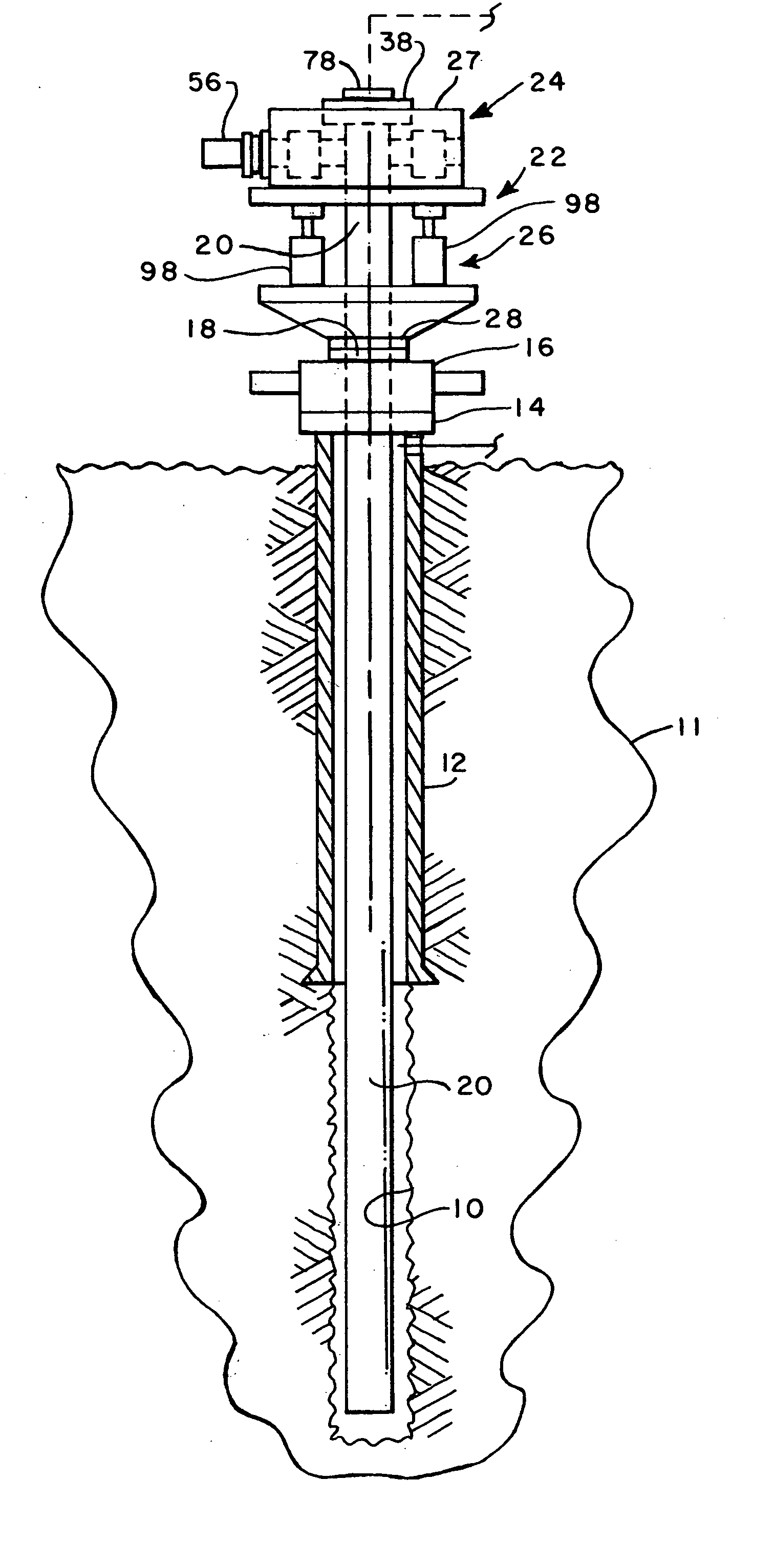
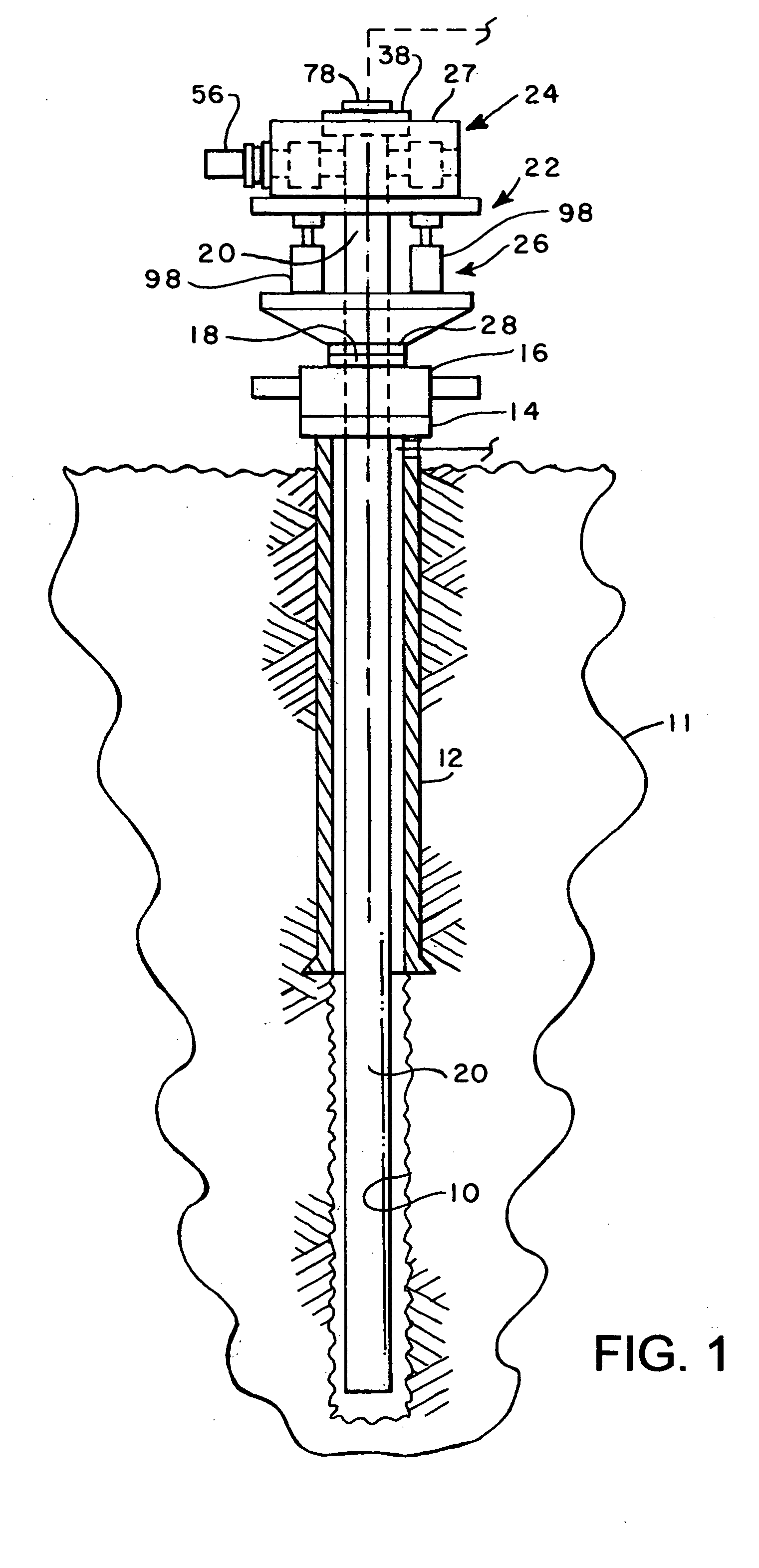
[0020] Referring to FIG. 1, there is illustrated, in somewhat schematic form, a wellbore 10 penetrating an earth formation 11 and having disposed in place a surface casing 12. Surface casing 12 extends to a wellhead structure including a support flange 14 and further structure mounted thereon, including, for example, a blowout preventer 16. Blowout preventer 16, preferably includes an upwardly facing mounting flange 18. The wellhead structure including the flange 14 and blowout preventer 16 are exemplary and are commonly in place during many types of wellbore operations including drilling and cementing operations, for example.

[0021] Referring further to FIG. 1, there is illustrated...


PUM


Abstract

A vibrator apparatus for inducing longitudinal vibrations in a well tubing or casing member for various operations, or for removing stuck tubing or casing. The apparatus includes a vibrator section with spaced apart rotatable shafts carrying eccentric weights and interconnected by timing gears. The shafts are driven by respective pressure fluid motors. The vibrator section is mounted on an isolator section including spaced apart pressure fluid cylinder assemblies for isolating vibrations generated by the apparatus from wellhead structure supporting the apparatus. A fluid flow circuit includes a pump, a manifold, flow control devices for generating fluid flow through the cylinder assemblies and accumulators for damping fluid pressure and flow fluctuations in the circuit.

Description

BACKGROUND OF THE INVENTION [0001] In the art of well drilling and completing operations there has been a long-standing need for apparatus which can effectively vibrate or oscillate a tubing or casing string for various purposes, including improving primary wellbore cementing operations, releasing stuck tubing or casing and other operations, such as fishing operations, gravel packing and workover operations and the like. However, several problems remain effectively unsolved with regard to the provision of vibrator apparatus which can be connected to the upper end of well tubing, including coil tubing, or casing, and impart oscillatory vibrational forces to such tubular members without damaging associated well structure and inducing vibration of the tubular member at a resonant frequency which provides for a more effective and less energy consuming operation. [0002] Effectively isolating vibrations induced by vibrator apparatus from associated well structure supporting the vibrator a...

Claims


Application Information

Patent Timeline
Patent Type & Authority Applications(United States)
IPC IPC(8): E21B28/00E21B31/00
CPCE21B31/005E21B28/00
Inventor WEBB, LLOYD A.SOUTHALL, THOMAS D.BIART, WAYNE M.BERG, ORVIE E.
Owner DHR SOLUTIONS
Why Eureka
Try Eureka