Method of manufacturing airtight vessel, and method of manufacturing image displaying apparatus

a technology of airtight vessels and displaying apparatuses, which is applied in the direction of heating types, tubes with screens, ventilation systems, etc., can solve the problems of frame being unable to maintain its shape by itself, insufficient mechanical rigidity, and becoming difficult to assemble the panel

Inactive Publication Date: 2005-07-21
CANON KK
View PDF13 Cites 3 Cited by
  • Summary
  • Abstract
  • Description
  • Claims
  • Application Information

AI Technical Summary

Benefits of technology

[0018] The present inventor assessed the possibility of using a member smaller in sectional size (e.g. sectional width) as the member for use in the external frame with a view to reducing the size of the screen frame (non-display area) and the cost of members. However, he found that a smaller sectional size of the frame member would result in insufficient mechanical rigidity. In other words, the frame would be unable to maintain its shape by itself. As a result, it would become difficult in assembling the panel to accurately align the external frame, which is the frame member, with desired positions in the face plate and the rear plate and assemble them. If the positional accuracy of the external frame is poor, the likelihood of impossibility to maintain a desired atmosphere in the internal space will increase, leading to a drop in yield.

Problems solved by technology

However, he found that a smaller sectional size of the frame member would result in insufficient mechanical rigidity.
In other words, the frame would be unable to maintain its shape by itself.
As a result, it would become difficult in assembling the panel to accurately align the external frame, which is the frame member, with desired positions in the face plate and the rear plate and assemble them.
If the positional accuracy of the external frame is poor, the likelihood of impossibility to maintain a desired atmosphere in the internal space will increase, leading to a drop in yield.

Method used


Image

  • Method of manufacturing airtight vessel, and method of manufacturing image displaying apparatus
  • Method of manufacturing airtight vessel, and method of manufacturing image displaying apparatus
  • Method of manufacturing airtight vessel, and method of manufacturing image displaying apparatus

Examples


first embodiment

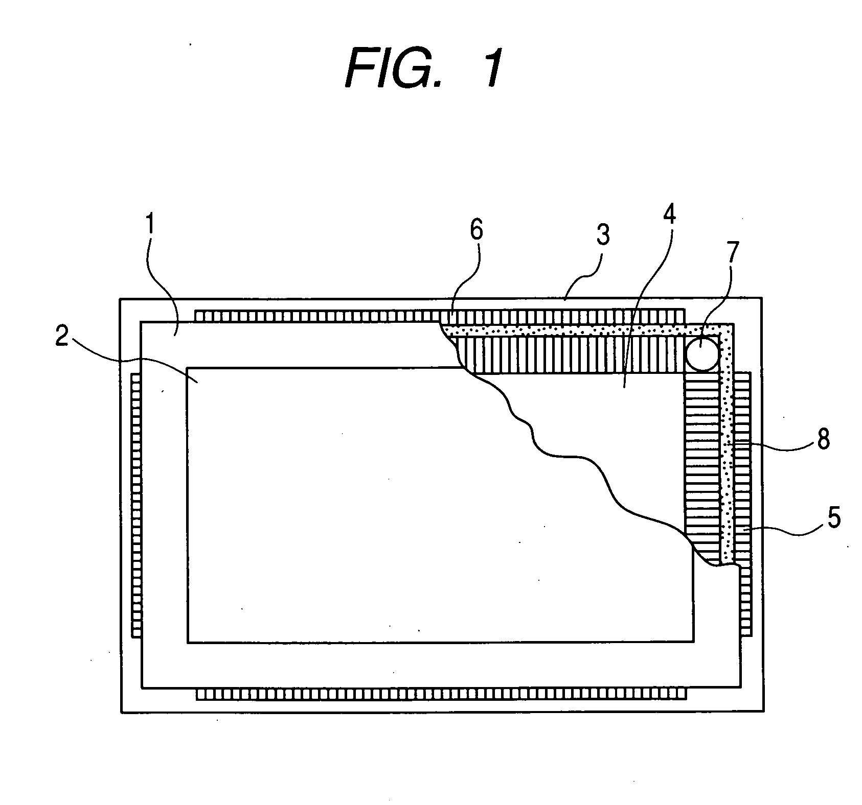
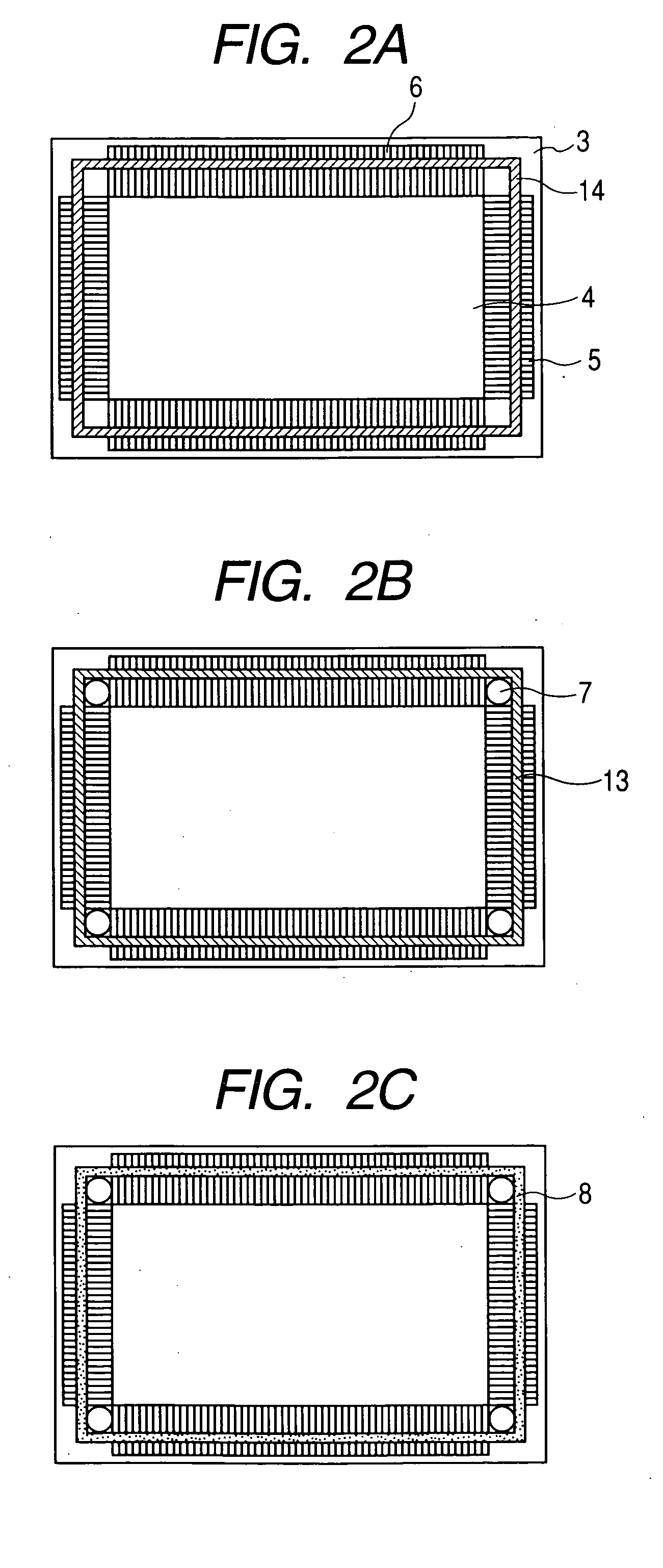
[0047] The first embodiment of the invention will now be described with reference to FIG. 1 through FIGS. 4A and 4B. In the figures, reference numeral 1 denotes a face plate; 2, an image display area; 3, a rear plate; 4, an electron source area; 5 and 6, extraction wirings; 7, positioning members; 8, a frame member; 11, an adhesion layer; 12a and 12b, low melting-point metal layers; 13a through 13c, base layers; and 14, an insulating layer. FIG. 4B shows the A-A′ section of FIG. 4A. Incidentally, the illustration of the insulating layer 14, the base layers 13a, 13b and 13c, and the low melting-point metal layer 12a is dispensed with in FIG. 4A.

[0048] In this embodiment, the face plate 1, the rear plate 3 and the frame member respectively correspond to the face plate 110, the rear plate 103 and the external frame 104 of the display panel in FIG. 10.

[0049] The image display area 2 of the face plate 1 consists of a fluorescent film (not shown), black stripes (or a black matrix) and a...

second embodiment

[0061]FIG. 5 shows how the frame member 8 and the rear plate 3 are aligned with each other in a second embodiment of the invention. In FIG. 5, reference numeral 51 denotes positioning members, and the same members as in FIG. 3 are denoted by respectively the same reference signs.

[0062] Each of the positioning members 51 consists of two ceramic-made cylindrical members linked to each other, but the two members may as well be separated from each other. The positioning members 51 are positioned in the four corners, each along two sides constituting one corner of the frame member 8, to perform positional restriction.

[0063] This embodiment is more effective than the first embodiment for a display panel required to have a large screen because a large frame member 8 can be more securely subjected to positional restriction in this way.

third embodiment

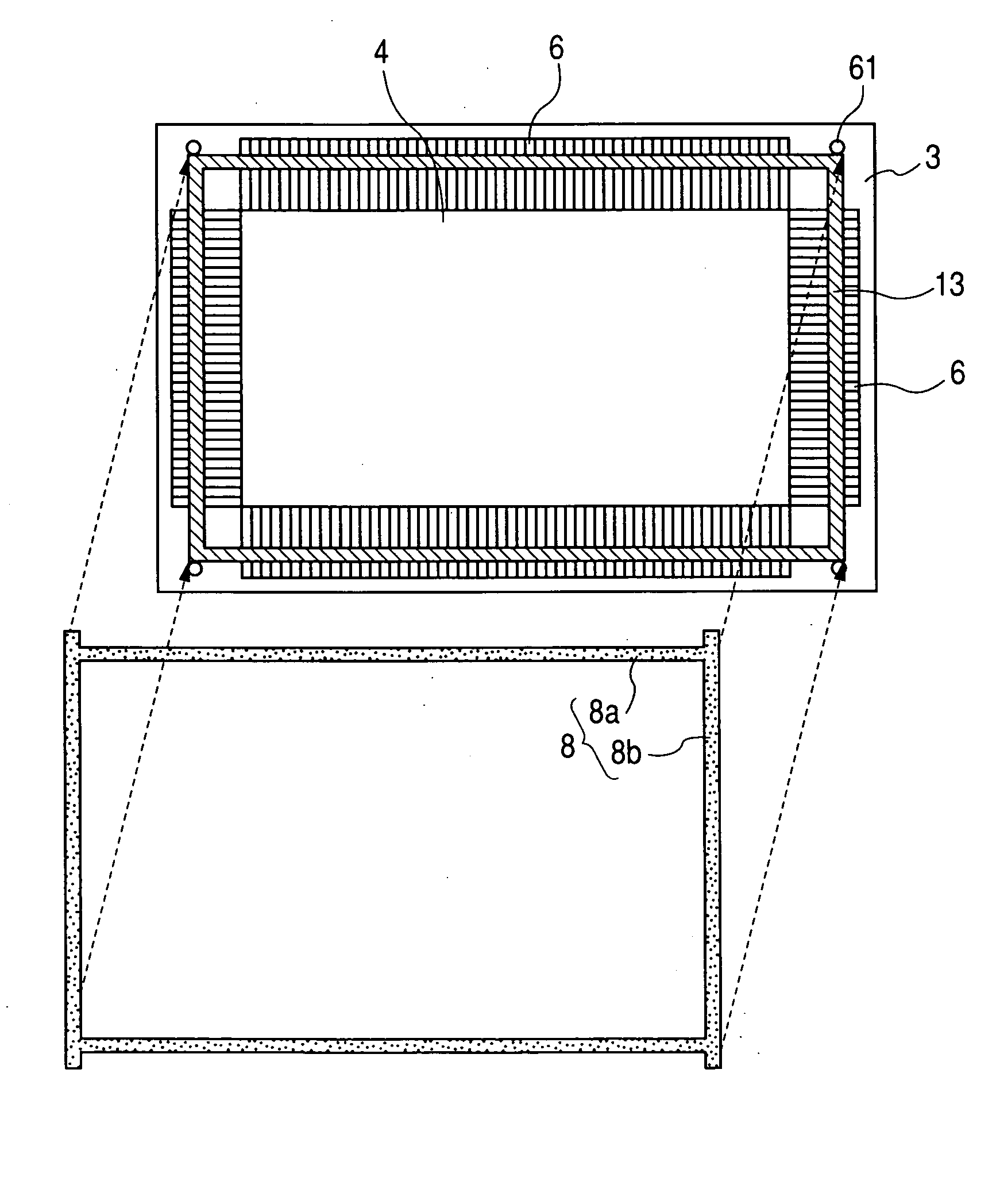
[0064]FIG. 6 shows how the frame member 8 and the rear plate 3 are aligned with each other in a third embodiment of the invention. In FIG. 6, reference numeral 61 denotes positioning pins, and, 62, fixing members. The same members as in FIG. 3 are denoted by respectively the same reference signs.

[0065] This embodiment is the same as the first embodiment except that the positioning pins 61 and the fixing members 62 are used as positioning members and that the frame member 8 is subjected to positional restriction outside it. More specifically, holes bored in the fixing members 62 fitted outside the four corners of the frame member 8 are snapped with a robot hand (not shown) onto the positioning pins 61 fitted to the corners of the rear plate 3. The positioning pins 61 and the fixing members 62 should preferably be formed of ceramics.

[0066] This embodiment, since the positioning members are fitted outside the frame member 8, requires care about degassing only when fabricating the vac...


PUM


Abstract

The present application discloses a method of manufacturing airtight vessel. More specifically, here is disclosed a method of manufacturing airtight vessel having two substrates, and a frame portion fixed to the two substrates and forming a prescribed space between the two substrates, the method comprising a step of keeping a frame member for the frame portion in a prescribed shape by applying a tension to at least a part of the frame member for the frame portion, and a step of adhering the frame member to at least one of the substrates in a state in which the prescribed shape is kept.

Description

BACKGROUND OF THE INVENTION [0001] 1. Field of the Invention [0002] The present invention relates to a method of manufacturing airtight vessel whose inside is to be kept airtight, and more particularly to a method of manufacturing airtight vessel which can be suitably applied to display panels of image displaying apparatus. The invention also relates to an image displaying apparatus, and a method of manufacturing image displaying apparatus. It also relates to a method of manufacturing television sets. [0003] 2. Related Background Art [0004] Usually, an image displaying apparatus utilizing electron emission requires an envelope for maintaining a vacuum ambience, an electron source provided with a plurality of electron-emitting devices and a drive circuit therefor, an image-forming member having a phosphor or the like which is caused to emit light by the collision of electrons, and accelerating electrodes for accelerating the motions of electrons towards the image-forming member and a...

Claims


Application Information

Patent Timeline
Patent Type & Authority Applications(United States)
IPC IPC(8): H01J9/24H01J9/26H01J9/40H01J29/86H01J31/12
CPCH01J9/261H01J9/241F24F13/28F24F7/04F24F2007/004
Inventor KAWASE, TOSHIMITSU
Owner CANON KK
Why Eureka
Try Eureka