
System and method for detecting a reversed battery cell in a battery pack

a reversed battery cell and battery pack technology, applied in the field of batteries, can solve the problems of large number of rechargeable batteries, catastrophic failure of the reversed battery cell(s), and associated problems of industrial and similar battery packs

Inactive Publication Date: 2005-07-21
MATHEWS ASSOCS
View PDF8 Cites 38 Cited by
  • Summary
  • Abstract
  • Description
  • Claims
  • Application Information

AI Technical Summary

Benefits of technology

[0007] It is therefore an object of the present invention to provide a battery pack formed from a number of cells in series and / or series / parallel configuration that allows the detection of a reversed battery cell.
[0013] The LED circuit could also be used in conjunction with the power switch circuit to provide a visual indication of the reversed cell during manufacturing of the battery pack. This approach prevents the battery pack from being discharged when a cell is reversed thereby preventing the reversed cell from being charged during battery discharge.

Problems solved by technology

Industrial batteries used in civilian and military applications often require large numbers of rechargeable batteries, such as lithium batteries.
In any event, associated problems with industrial and similar battery packs exist.
A potential problem exists if one or more battery cells in any one string are inadvertently installed backwards, i.e., reversed.
That battery cell or cells would be charged by the discharge current of the other battery cells in that string, possibly leading to catastrophic failure of the reversed battery cell(s).
A simple terminal voltage test of a battery cell usually is not reliable.
Other proposals for detecting reversed battery cells in battery charging systems are not as applicable to battery packs.
Although these systems provide some reversed battery cell detection in a battery charger or similar systems, they have not been wholly adequate for a battery pack with a number of battery cells in which one battery cell could be reversed causing problems for the entire battery pack.

Method used


Image

  • System and method for detecting a reversed battery cell in a battery pack
  • System and method for detecting a reversed battery cell in a battery pack
  • System and method for detecting a reversed battery cell in a battery pack

Examples


Embodiment Construction

[0025] The present invention will now be described more fully hereinafter with reference to the accompanying drawings, in which preferred embodiments of the invention are shown. This invention may, however, be embodied in many different forms and should not be construed as limited to the embodiments set forth herein. Rather, these embodiments are provided so that this disclosure will be thorough and complete, and will fully convey the scope of the invention to those skilled in the art. Like numbers refer to like elements throughout, and prime notation is used to indicate similar elements in alternative embodiments.

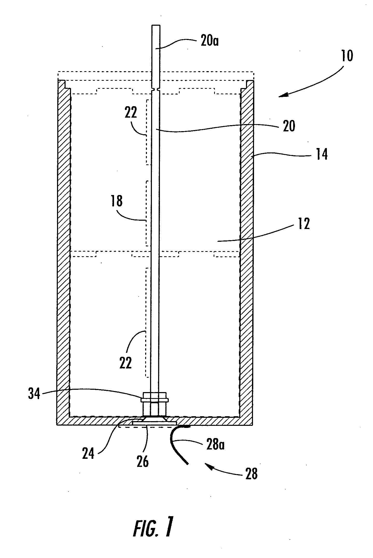
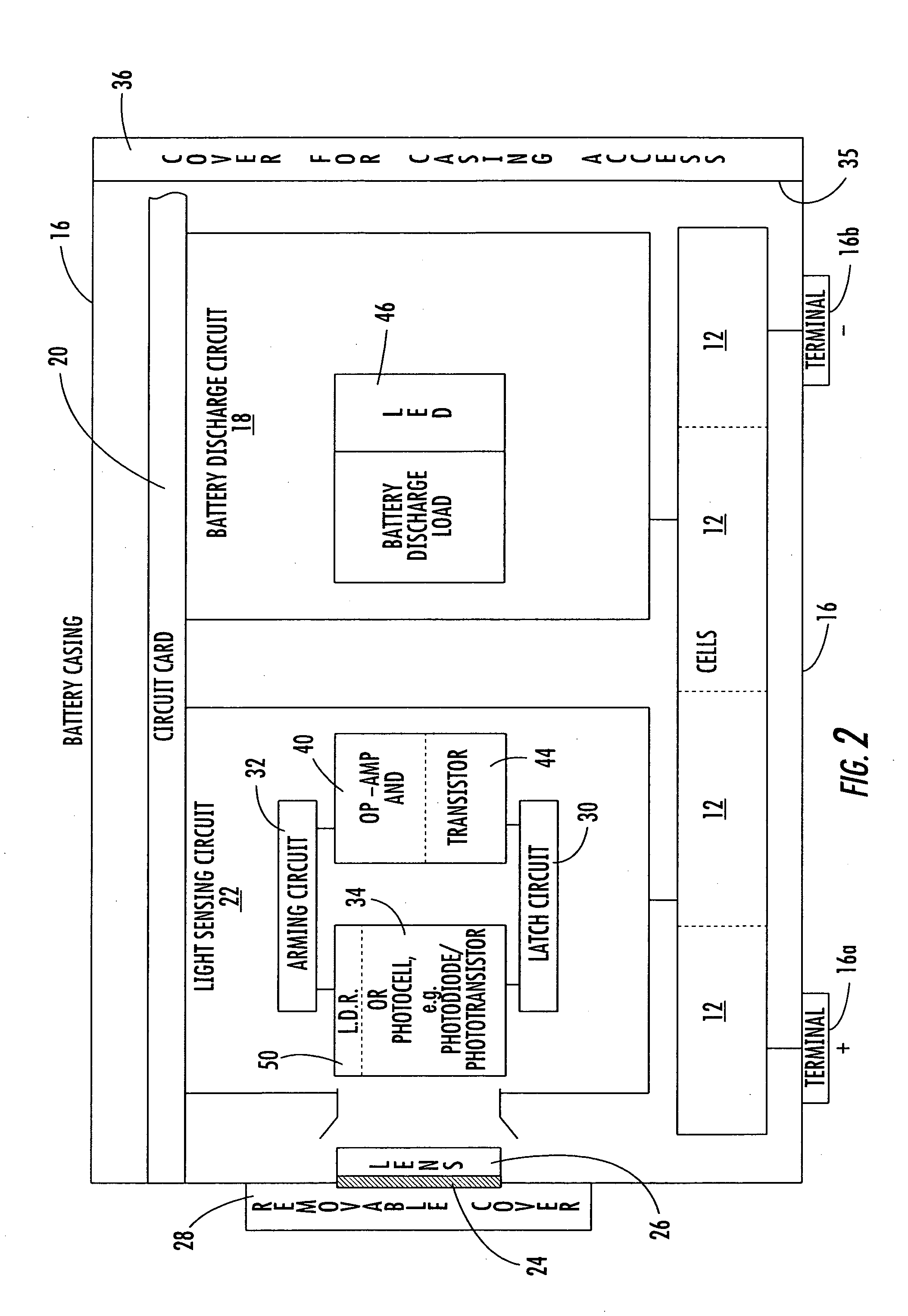
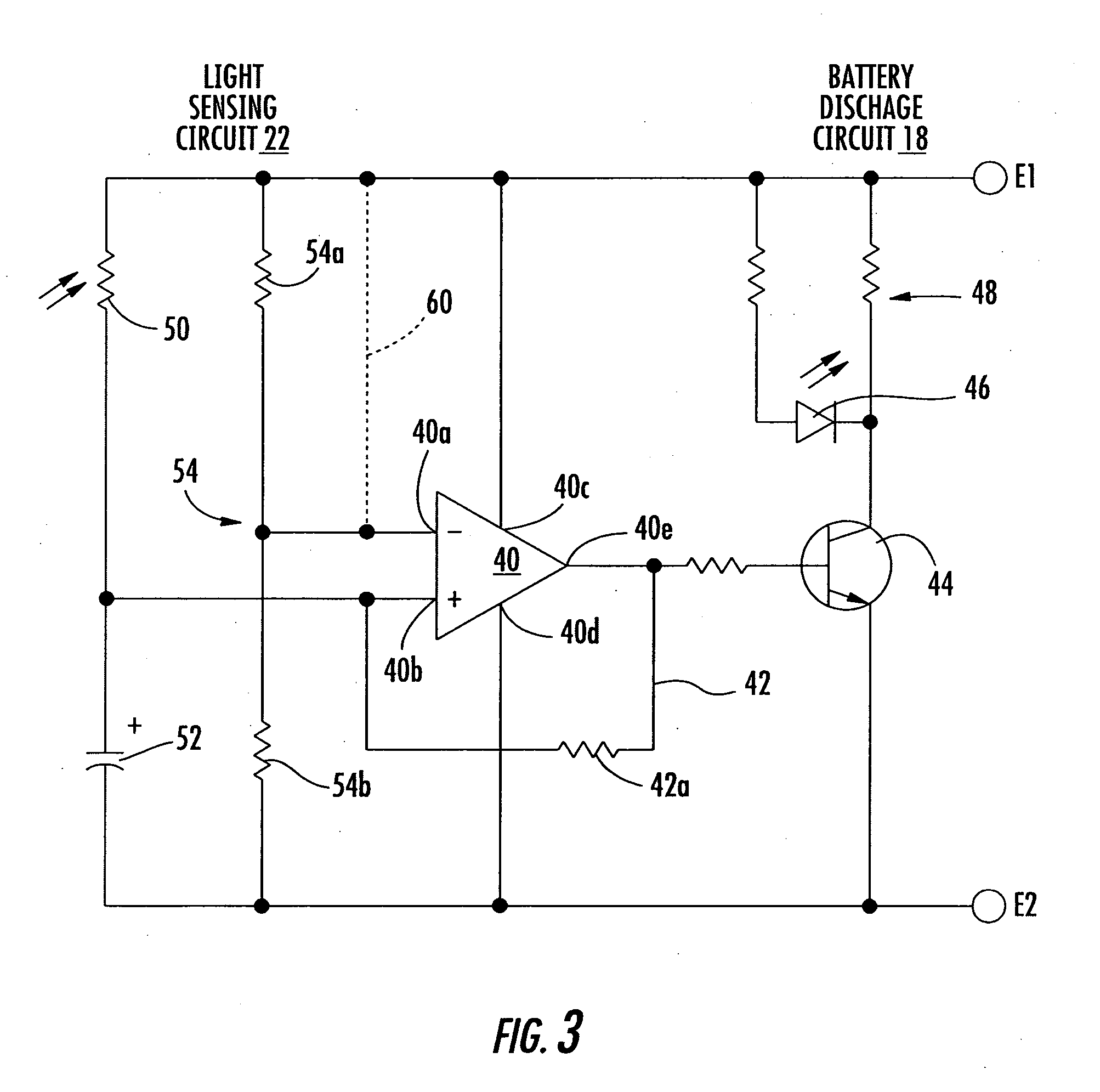
[0026] For purposes of description and background, battery discharge circuits disclosed in commonly assigned U.S. patent application Ser. Nos. 10 / 452,738 and 10 / 694,635 (the respective '738 and '635 applications) will be set forth relative to FIGS. 1-7 as examples of the types of circuits and cells that advantageously could be combined for use with the present invention. ...


PUM


Abstract

A system and method for detecting a reversed battery cell within a battery pack includes battery cells connected together and forming a battery pack and battery output. A transistor circuit is operatively connected to the battery cells and operative for determining when a voltage condition occurs indicative of a reversed battery cell within the battery pack. An indication circuit is operatively connected to the transistor circuit for indicating a reversed battery cell in the battery pack.

Description

RELATED APPLICATION [0001] This application is based upon prior filed copending provisional application Ser. No. 60 / 537,666 filed Jan. 20, 2004.FIELD OF THE INVENTION [0002] This invention relates to batteries, and more particularly, the present invention relates to a system and method for detecting a reversed battery cell in a battery pack. BACKGROUND OF THE INVENTION [0003] Industrial batteries used in civilian and military applications often require large numbers of rechargeable batteries, such as lithium batteries. Often smaller batteries are arranged together to form a larger battery pack, which could include primary and secondary batteries. Often the voltage requirements are met by stacking series connected battery cells and adding parallel strings of battery cells to meet the voltage requirements and / or any necessary cut-off voltage. [0004] In any event, associated problems with industrial and similar battery packs exist. For example, in order to meet battery pack size and pe...

Claims


Application Information

Patent Timeline
IPC IPC(8): H02J7/00
CPCH02J7/0021H02J7/0034H02J7/0013H02J7/0048
Inventor KAMENOFF, ROBERT
Owner MATHEWS ASSOCS
Learn More