
Measurement of object deformation with optical profiler

a technology of object deformation and profiler, which is applied in the field of scanning interferometry, can solve the problems of inability to recover object-motion information, inability to detect object motion, and inability to accurately detect object motion, etc., and achieve the effect of improving the accuracy of the instrumen

Active Publication Date: 2005-07-21
BRUKER NANO INC
View PDF2 Cites 31 Cited by
  • Summary
  • Abstract
  • Description
  • Claims
  • Application Information

AI Technical Summary

Benefits of technology

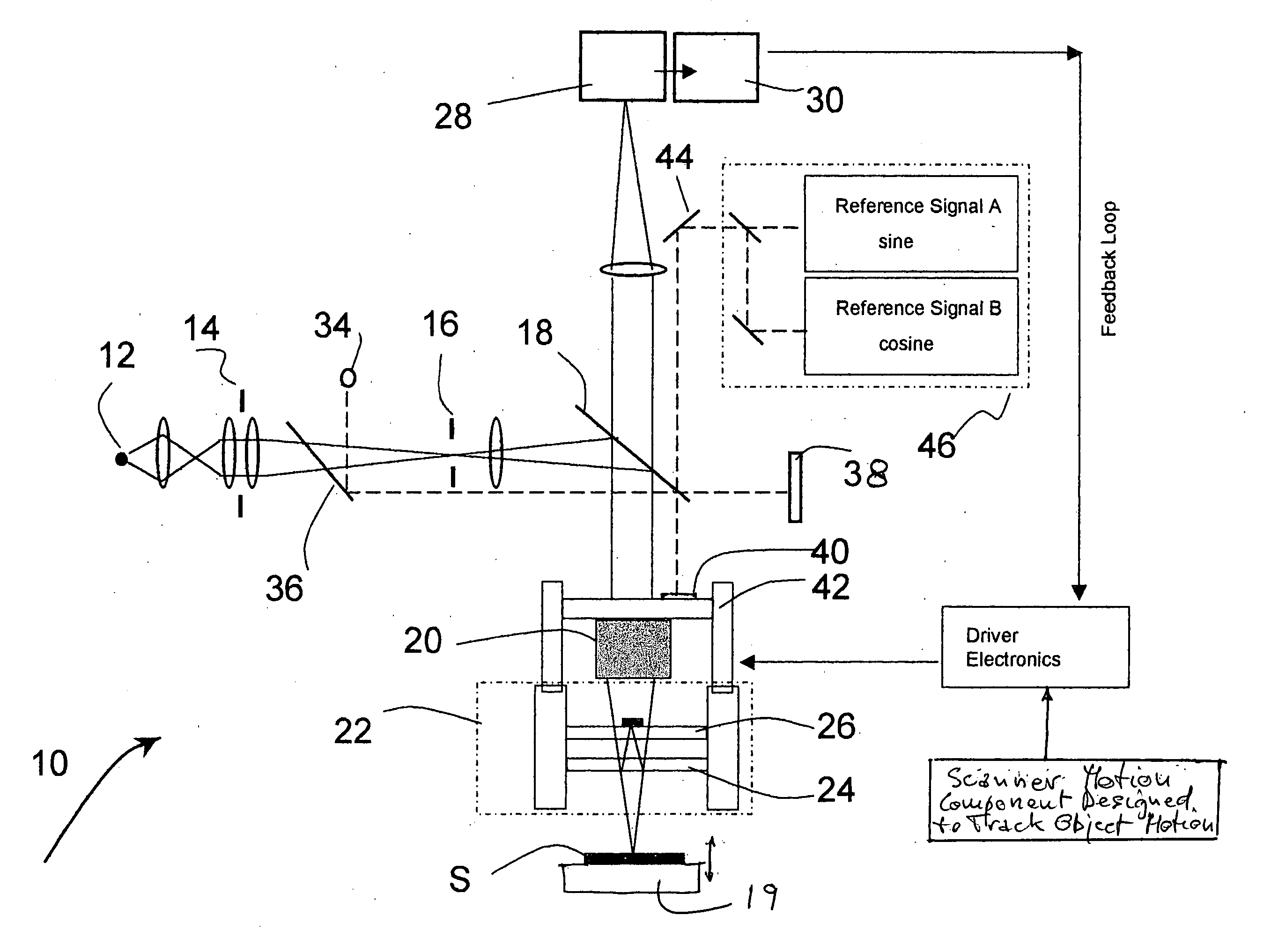
The invention is a method for monitoring object motion using interferometric profilometry. It involves modifying the interferometer to maintain the phase variation between frames observed during a scan within the acceptable limits of the algorithm used to calculate phase changes. The scanner motion is then manipulated to deliver optimal measurement results as the scanner progresses in its motion. The resulting phase steps measured by the detector are used to recover the object motion by tracking the observed phase change from frame to frame. The invention can be applied to interferometers that produce fringe shifts by scanning or by other means, and it can be adjusted automatically or through feedback to deliver optimal measurement results. The method is particularly useful for measuring object motions of a linear or harmonic nature.

Problems solved by technology

These techniques are limited in their applicability by the relatively long data-transfer times associated with area detectors.
The limitation of this technique lies in the fact that the relative phase of vibrations at consecutive data points can be lost and therefore the recovery of object-motion information may be incorrect.
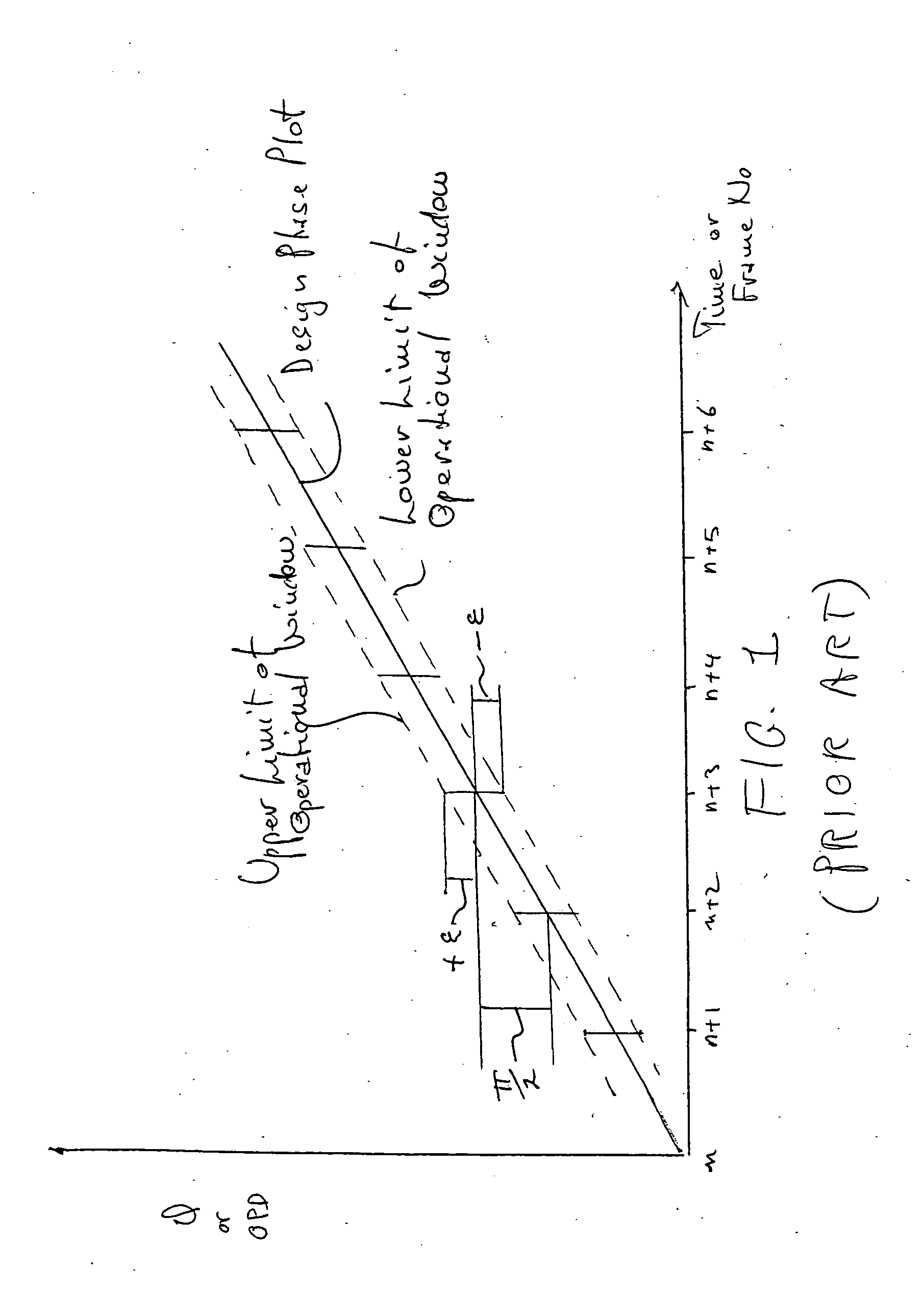
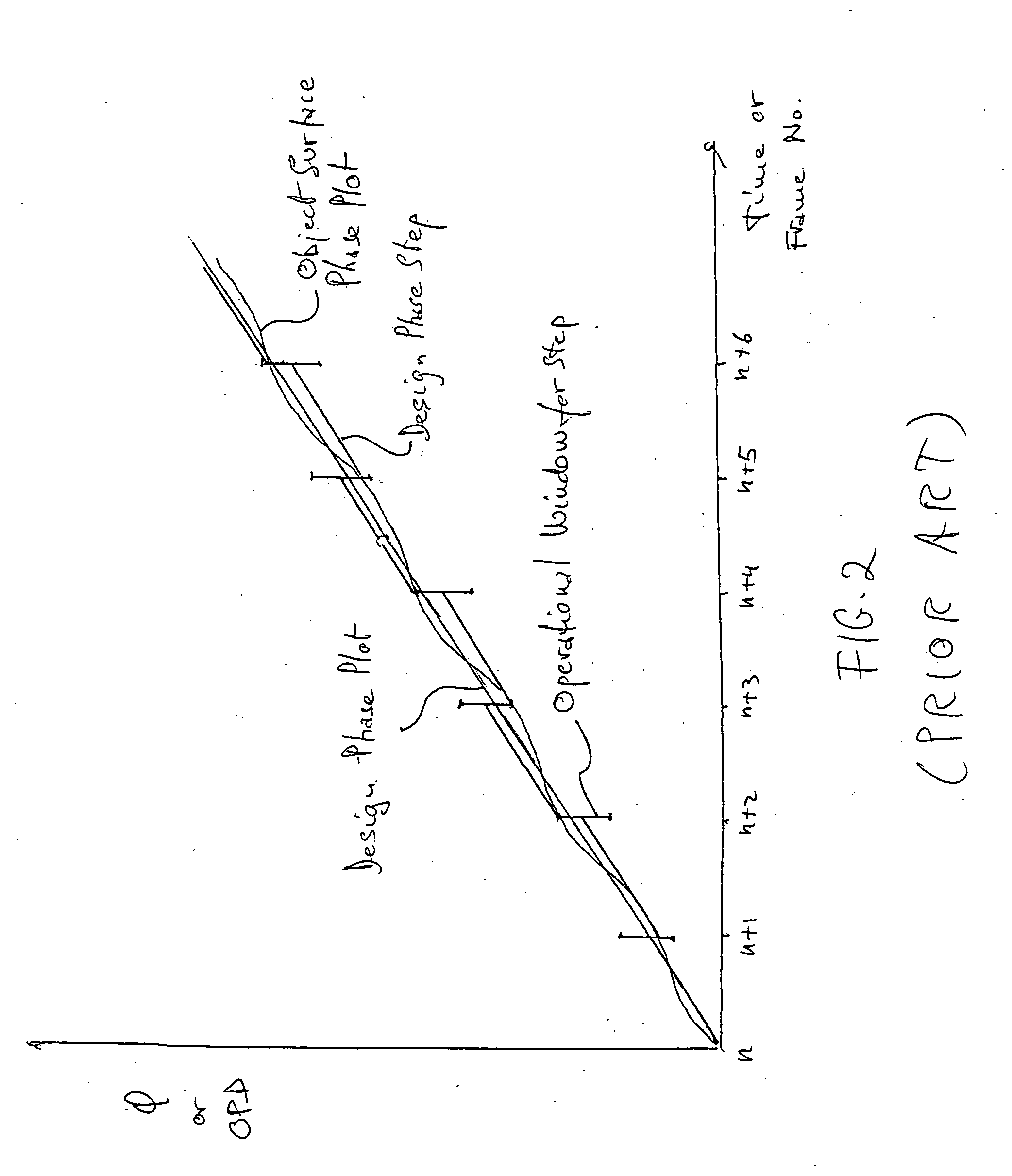
The optical profilometric techniques traditionally used to determine object shape based on spatial or temporal analysis of fringe patterns are not always suitable for detecting object motion, as herein defined, because of phase-change constraints inherent with the algorithms associated with each technique.
If the object motion materially alters the actual phase change between the object and the reference surfaces, the algorithm will produce unreliable results.
Thus, conventional profilometry is inadequate to measure motion when the object motion is characterized by a range of amplitudes or frequencies that are not suitable for the algorithms utilized in the system (and thus the information cannot be processed in converging fashion to describe the object motion).
Recent profilometric technique improvements, such as the use of a reference signal (described in U.S. Publication No. 2002-0196450, incorporated here by reference), addressed measurement precision but did not provide an avenue of compensation for object motion.
Although the use of a reference signal makes it possible to correct scanner deviations from nominal performance, the computational constraints of the algorithms still prevent its general application in the measurement of object motion.
Accordingly, interferometric analysis would not allow accurate recovery of the object motion.
Therefore, to the extent that interferometric profilers are used for object characterization, conventional analysis approaches do not generally allow for proper monitoring of object motion on the basis of actual scanner position history.

Method used


Image

  • Measurement of object deformation with optical profiler
  • Measurement of object deformation with optical profiler
  • Measurement of object deformation with optical profiler

Examples


Embodiment Construction

[0038] The inventive concept of this disclosure resides in the idea of appropriately introducing an additional component to the scanning motion in the interferometric profiler to produce phase changes between acquisition frames that ensure the proper utilization of the algorithms selected for interferometric analysis. The invention preferably utilizes narrow-band light sources to cover the entire range of operation of the scanner, as is commonly done in prior-art profilers. As is well understood, if a wider band light is used, the range of operation is restricted to the coherence of the light. Accordingly, the invention is suitable for implementation with most types of conventional interferometric techniques. In addition, the invention preferably also utilizes a narrow-band reference signal to accurately track scanner motion (or other equivalent means to track induced fringe motion).

[0039] The terms “interferogram,”“interferometric” and “interferometric fringes” are used with the s...


PUM


Abstract

An interferometric profiler is used to measure object motion by modifying the motion of the scanner so that the phase variation at each scanning step is kept within the acceptable limits of the algorithm used to calculate phase changes. The scanner motion is so manipulated on the basis of prior knowledge about the nature of the object motion, or knowledge obtained by pre-calibration, or by real-time feedback based on current measurements. The object motion is recovered from the scanning information by subtracting the scanner position from the object position as it evolves during the scan.

Description

BACKGROUND OF THE INVENTION [0001] 1. Field of the Invention [0002] This invention relates in general to the field of scanning interferometry and, in particular, to a new approach for measuring sample deformations occurring during interferometric measurements. [0003] 2. Description of the Prior Art [0004] Recent developments in micro-optics and micro-electro-mechanical systems (MEMS) technology produced a variety of engineered micro-elements, ranging from gears and mirror arrays to membranes, resonators and accelerators. Inasmuch as these micro-elements (which vary in size from micrometers to millimeters) are susceptible to shape changes while in operation, a need has arisen for measuring not only their static shape but also their motion behavior (that is, the vertical displacement due to operational motion and shape changes due to vibration, deformation, and the like). [0005] Traditional surface profilometry has dealt with the characterization of the surface profile of a static obj...

Claims


Application Information

Patent Timeline
Patent Type & Authority Applications(United States)
IPC IPC(8): G01B11/16
CPCG01B11/161
Inventor SCHMIT, JOANNAUNRUH, PAUL R.NOVAK, ERIK L.
Owner BRUKER NANO INC
Learn More