High gradient-field recording head for perpendicular magnetic recording and fabrication method therefore

a perpendicular magnetic and recording head technology, applied in the direction of manufacturing head surfaces, instruments, manufacturing tools, etc., can solve the problems of deterioration of the magnetic field gradient in the profile of a perpendicular magnetic field, and achieve the effects of reducing the magnetic field gradient, reducing the leakage magnetic field, and increasing the local leakage magnetic field

Inactive Publication Date: 2005-07-21
HITACHI GLOBAL STORAGE TECH JAPAN LTD
View PDF4 Cites 11 Cited by
  • Summary
  • Abstract
  • Description
  • Claims
  • Application Information

AI Technical Summary

Benefits of technology

[0008] In the above prior art, the leakage magnetic field is locally increased due to the influence of abrupt flux enhancing in the flux enhanced part in the main pole and the pole tip and particularly, the flux enhanced end in which the cross-sectional area of the main pole is smallest in the flux enhanced part, resulting in deterioration of the magnetic field gradient in a profile of a perpendicular magnetic field. In addition, the leakage magnetic field from the front or side surface of the main pole or the pole tip will also reduce the magnetic field gradient. An object of the present invention is to improve a magnetic field gradient in a distribution of a perpendicular magnetic field which writes the boundary of a bit cell, that is, a magnetic field gradient on the trailing side of a profile of a perpendicular magnetic field in the down track direction and a magnetic field gradient near both ends of a track of a profile of a perpendicular magnetic field in the cross track direction and to realize a high areal recording density by considering arrangement of the flux enhanced part or the flux enhanced end of a main pole or a pole tip and the front or side surface of the main pole or the pole tip.
[0009] In the present invention, part or all of the flux enhanced part or the flux enhanced end of a main pole or a pole tip is arranged on the leading side rather than a vertical plane including the trailing edge of the air bearing surface of the main pole so as to improve a magnetic field gradient of a profile of a perpendicular magnetic field on the trailing side and near both ends of a track width. In addition, the front or side surface of the main pole or the pole tip is arranged to the center of the main pole so as to improve a magnetic field gradient of the profile of a perpendicular magnetic field on the trailing side and near both ends of the track width.

Problems solved by technology

In the above prior art, the leakage magnetic field is locally increased due to the influence of abrupt flux enhancing in the flux enhanced part in the main pole and the pole tip and particularly, the flux enhanced end in which the cross-sectional area of the main pole is smallest in the flux enhanced part, resulting in deterioration of the magnetic field gradient in a profile of a perpendicular magnetic field.

Method used


Image

  • High gradient-field recording head for perpendicular magnetic recording and fabrication method therefore
  • High gradient-field recording head for perpendicular magnetic recording and fabrication method therefore
  • High gradient-field recording head for perpendicular magnetic recording and fabrication method therefore

Examples


embodiment 1

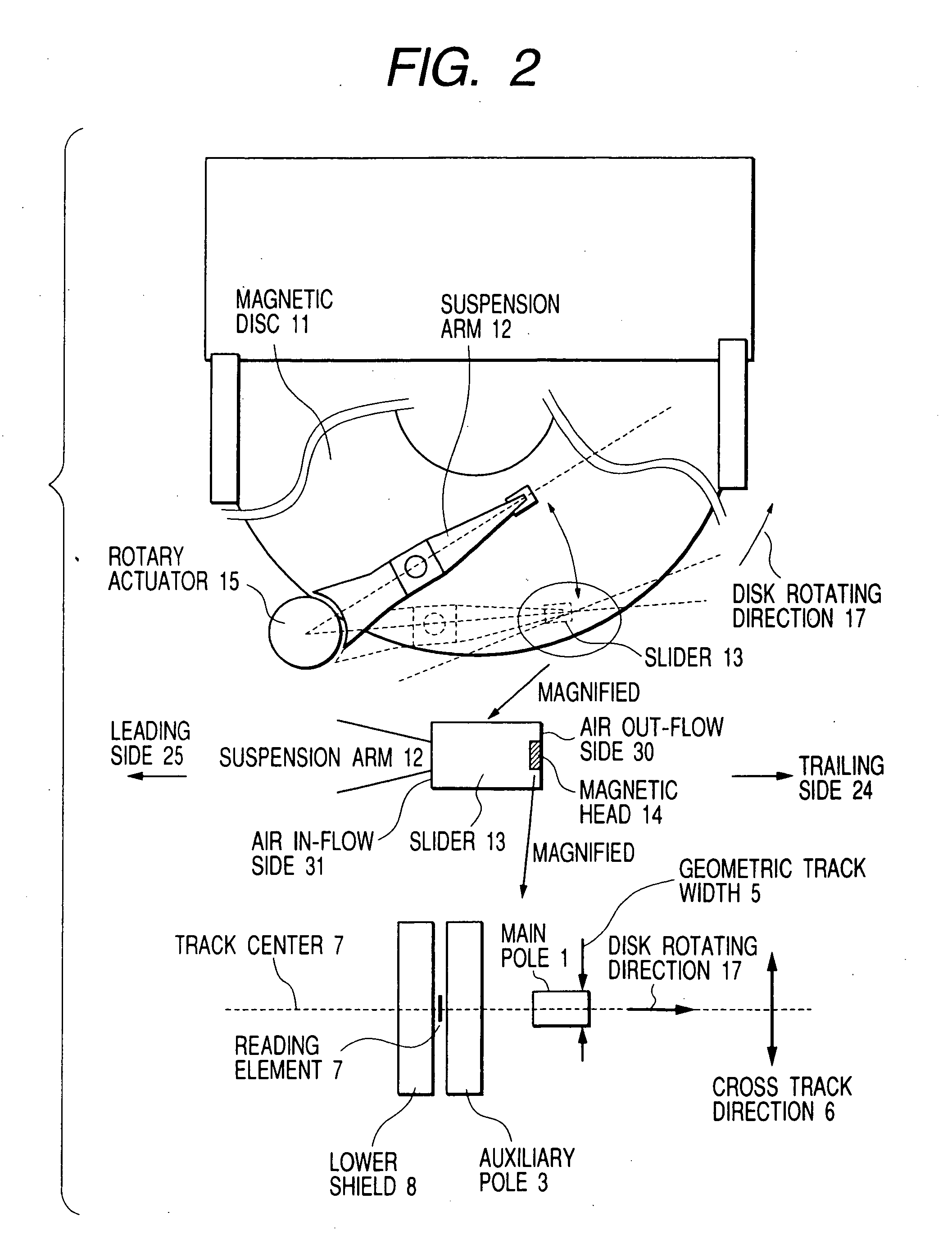
[0034] Embodiments of the present invention will be described hereinbelow with the drawings. FIG. 2 shows a schematic view of a magnetic disk apparatus using the present invention (provided that the magnification of the drawing is not uniform). The magnetic disk unit reads and writes a magnetization signal on a magnetic disk 11 by a magnetic head 14 attached to a slider 13 fixed onto the front end of a suspension arm 12. The direction of an air in-flow side 31.of the slider 13 is called a leading side. The direction of an air out-flow side 30 is called a trailing side. The direction to define a geometric track width 5 orthogonal to a disk rotating direction 17 is called a cross track direction 6. Gimbals, not shown, are formed at the front end of the suspension arm 12. FIG. 3 shows schematic views of the magnetic disk apparatus.

[0035]FIG. 4 shows a schematic view of perpendicular recording. The downstream side in the rotating direction of a perpendicular magnetic recording medium i...

embodiment 2

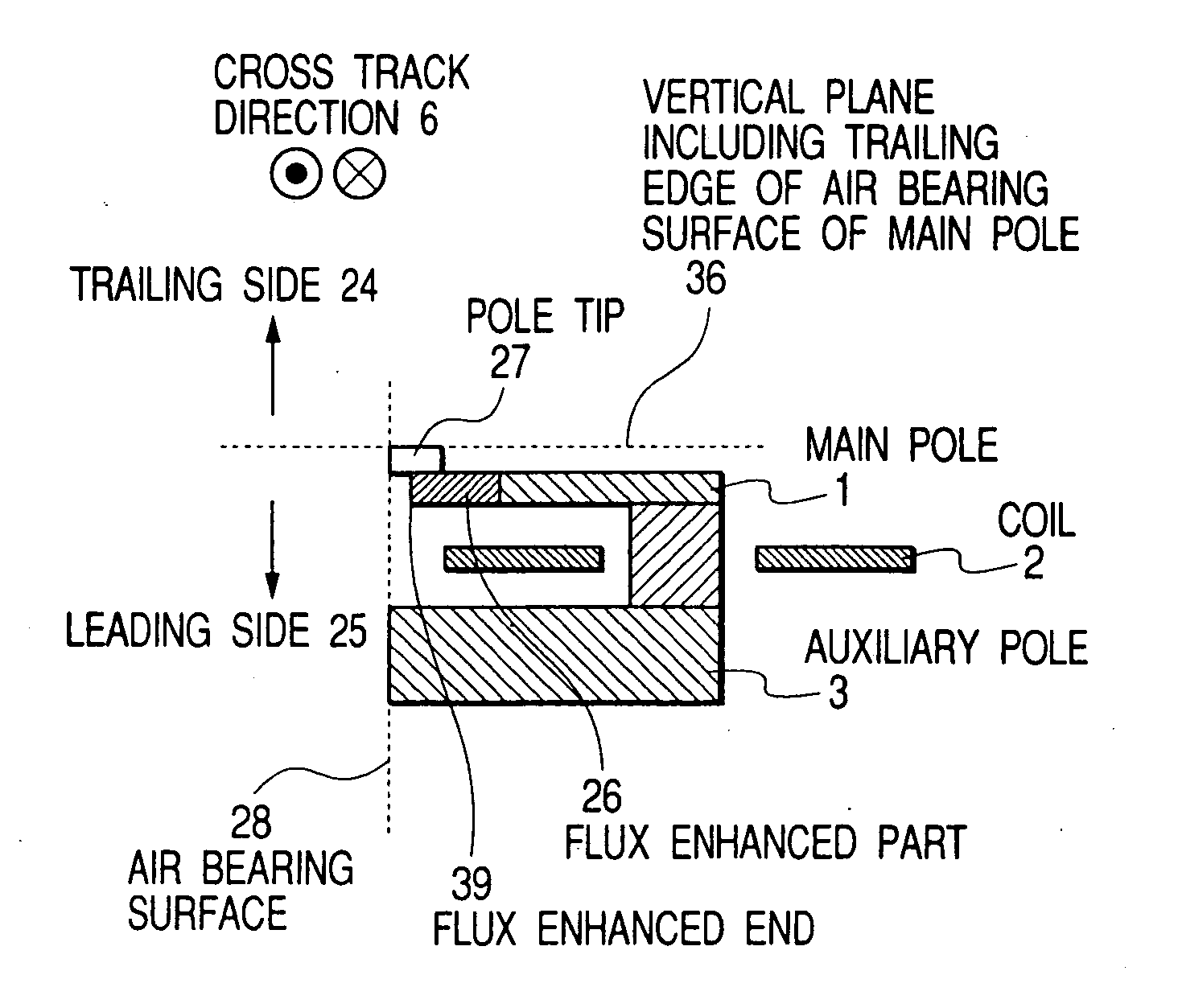
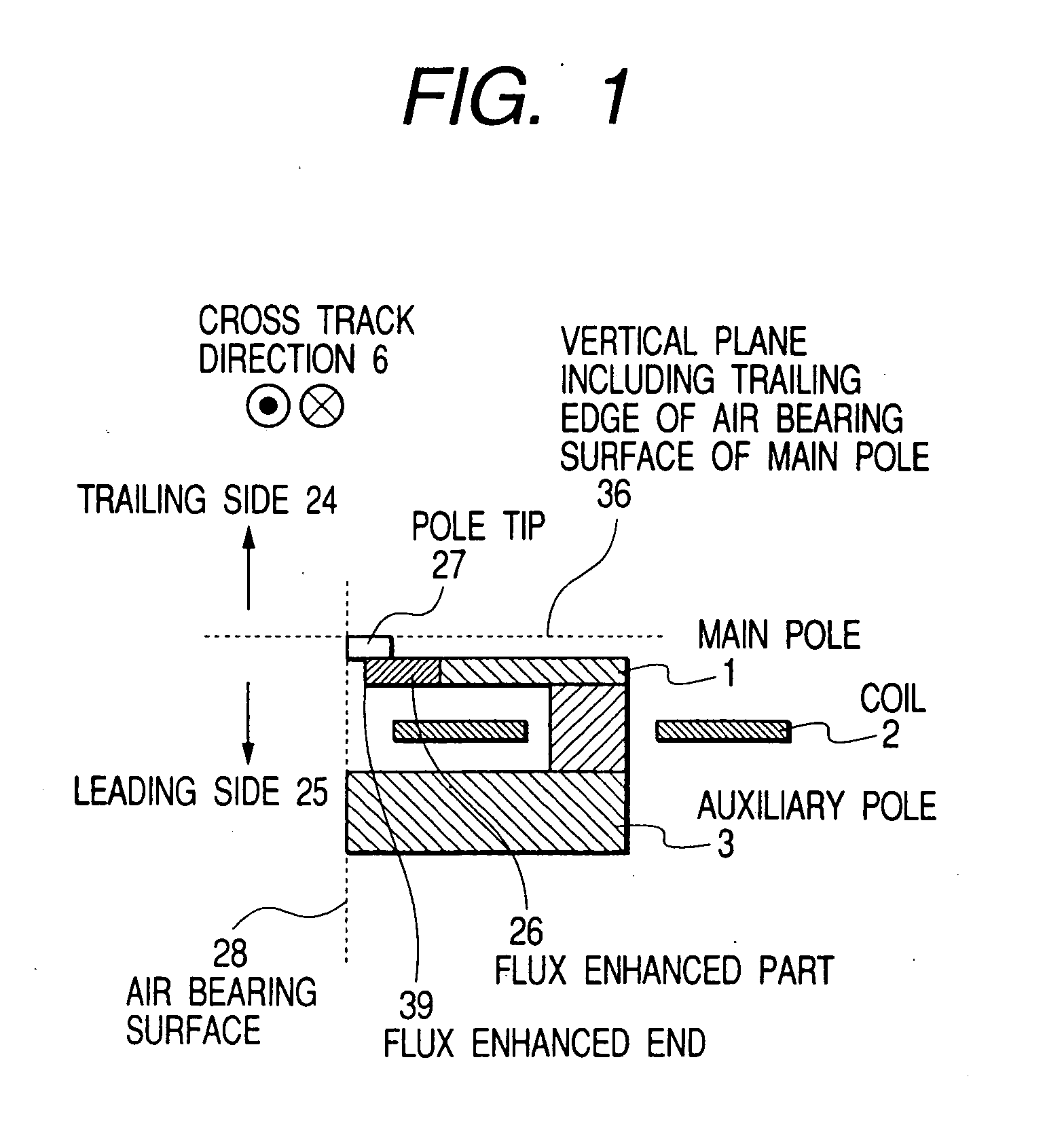
[0044] FIGS. 13 to 17 list the embodiments of the present invention. In FIG. 13, there are shown structures of the main pole not having the pole tip. In FIG. 13(1), the front surface of the main pole on the trailing side intersecting the air bearing surface of the main pole is tilted so that the flux enhanced part 26 and the flux enhanced end 39 are arranged on the leading side rather than a vertical plane 36 in parallel with the cross track direction including the trailing edge of the air bearing surface of the main pole. In FIG. 13(2), the front surface of the main pole on the trailing side is arranged on the leading side by leaving a portion to define a track width and the trailing edge, and at the same time, the flux enhanced part 26 and the flux enhanced end 39 are arranged on the leading side rather than the vertical plane 36 in parallel with the cross track direction including the trailing edge of the air bearing surface of the main pole. Here, the front surface of the main p...

embodiment 3

[0048] FIGS. 14 to 16 respectively show structures when the main pole has the pole tip 27. When the pole tip is provided, it can be expected that the accuracy of the track width in the production process is enhanced, and magnetic domain control and a high Bs material such as 55% Fe-45% Ni having a saturation magnetic flux density of 1.6T or CoNiFe having a saturation magnetic flux density of 2.2T, or the like are used to improve the magnetic field intensity. In addition, the distance between the main pole and the soft magnetic underlayer is adjusted or the contact area of the pole tip with the main pole is adjusted, whereby the magnetic field intensity can be increased. Also in the case that the main pole has the pole tip 27, in order to prevent the leakage magnetic field, an arrangement in which the flux enhanced part 26 and the flux enhanced end 39 are as far as possible from the trailing edge of the pole tip is considered. In FIGS. 14(1) and 14(2), the flux enhanced part 26 and t...


PUM

PropertyMeasurementUnit
thicknessaaaaaaaaaa
widthaaaaaaaaaa
saturation magnetic flux densityaaaaaaaaaa

Abstract

A thin film magnetic head for perpendicular recording of a single-pole type has a flux enhanced part and a flux enhanced end arranged on a leading side of the main pole parallel with the cross track direction. The side surface of the main pole intersecting the cross track direction is arranged on the track center side perpendicular to the track width. The field gradient of a perpendicular magnetic field on the trailing side of the main pole and near both ends of the track is made steep to realize a higher areal recording density. The head is fabricated by forming a first resist pattern on an inorganic insulating layer. A slope is formed on the inorganic insulating layer with the resist pattern as a mask. A second resist pattern is then formed on the inorganic insulating layer to form a magnetic layer on the inorganic insulating layer.

Description

BACKGROUND OF THE INVENTION [0001] 1. Field of the Invention [0002] The present invention relates to a magnetic head for perpendicular recording and a magnetic disk apparatus equipped with the magnetic head for perpendicular recording. [0003] 2. Description of the Related Art [0004] To increase a recording capacity per unit area of a magnetic disk, the bit length and the track width must be reduced to decrease the size of one bit cell as a minimum unit of recording information. In the current longitudinal recording system, however, there arises the problem that bit cell reduction loses a written signal due to the influence of thermal fluctuation. To solve this problem, a perpendicular recording system magnetizes a medium in the perpendicular direction to write signal information. [0005] The recording head of a magnetic disk apparatus writes signal information onto a medium. In the perpendicular recording system, there are a system which uses a double-layered perpendicular medium hav...

Claims


Application Information

Patent Timeline
Patent Type & Authority Applications(United States)
IPC IPC(8): G11B5/667G11B5/00G11B5/012G11B5/127G11B5/187G11B5/31G11B5/48
CPCG11B5/012G11B5/1278G11B5/187G11B5/4886Y10T29/49048Y10T29/49044Y10T29/49043Y10T29/49052Y10T29/49046G11B2005/0029
Inventor KURODA, ATSUKOMOCHIZUKI, MASAFUMI
Owner HITACHI GLOBAL STORAGE TECH JAPAN LTD
Why Eureka
Try Eureka