Recurrent distribution network with input boundary limiters

a technology of boundary limiters and distribution networks, applied in lighting and heating apparatus, heating types, instruments, etc., can solve the problems of not being completely satisfactory in the foregoing devices, systems and methods

Inactive Publication Date: 2005-07-21
DYNAMIC ENERGY SYST
View PDF23 Cites 6 Cited by
  • Summary
  • Abstract
  • Description
  • Claims
  • Application Information

AI Technical Summary

Benefits of technology

[0011] In one aspect, the present invention provides a control apparatus for controlling a controlled process variable in a system. The control apparatus comprises a plurality of cooperative distribution hubs, each coupled to an associated controllable output device that affects the controlled process variable. The apparatus includes a corresponding plurality of connection hubs, each inputting information to a corresponding distribution hub and coupled to a plurality of boundary limiting devices. Each boundary limiting device receives at least an input signal indicative of a corresponding dependent process variable and includes limiting means for comparing the input signal to low and high boundary limits and sending means for sending output signals to the connection hub. Also provided are means for sending a global request to adjust the controlled process variable, to the plurality of cooperating distribution hubs, adjusting means for the plurality of cooperating distribution hubs to cooperatively adjust at least one of the controllable output devices to adjust the controlled process variable using heuristic rules, responsive to the global request, and based on the information.
[0012] In another aspect the inven...

Problems solved by technology

None of the foregoing devices, systems, and methods have been found to be completely satisfactory, however, in addressing or controlling the economic distribution of resources within mul...

Method used


Image

  • Recurrent distribution network with input boundary limiters
  • Recurrent distribution network with input boundary limiters
  • Recurrent distribution network with input boundary limiters

Examples


example 1

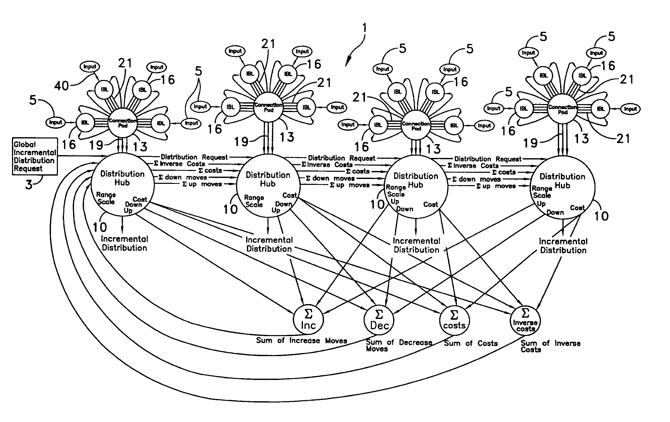
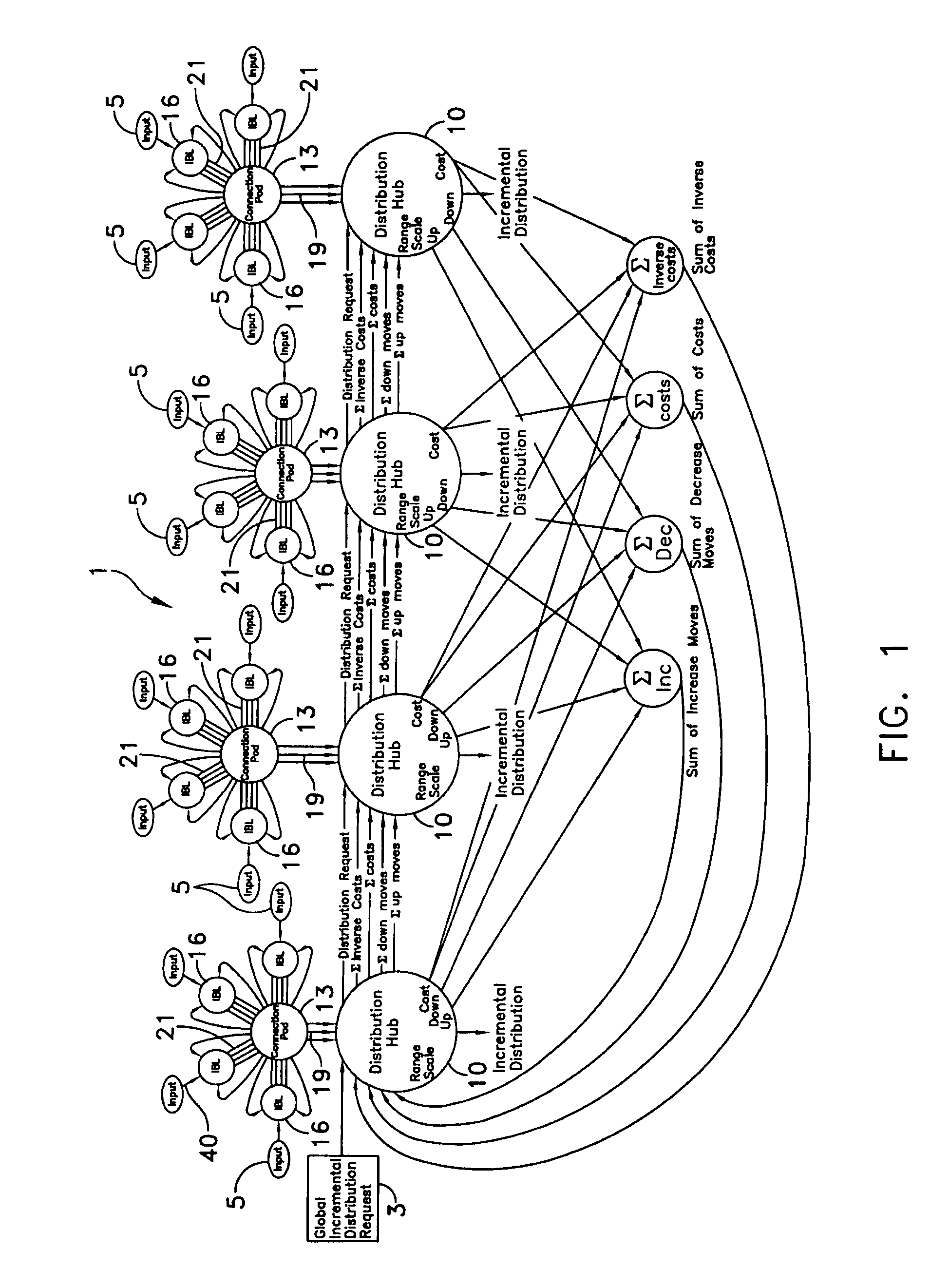
[0065] Referring to FIG. 15, a control application for an exemplary steam generating system is schematically illustrated employing a recurrent distribution network 1 formed and operated in accordance with the invention. In this exemplary application, only two distribution hubs 10a and 10b are connected to two controllable output devices—fuel control valves 9a and 9b respectively. For clarity and brevity, many of the recurrent feedback connections illustrated in FIG. 1 are not shown in FIG. 15. A proportional, integral and derivative controller, PID 50, with an incremental output, is used to generate global distribution requests 3 to recurrent distribution network 1. If measured header pressure 56 from a steam header is less than set-point or below specified or desired values, PID controller 50 requests an increase in header pressure. PID controller 50 may be conventional. Such a request manifests itself as a global distribution request 3 that, in turn, requests an increase in total ...


PUM


Abstract

A recurrent distribution network provides an embedded, cost-based decision mechanism for a real-time, closed-loop process control system that outputs to multiple controllable output devices while observing numerous input constraints. A global incremental distribution request to increase or decrease a controlled process variable is accepted by a recurrent neural network. The network iteratively solves and applies a distribution of a global incremental request to multiple controllable output devices based on individual incremental unit costs, output ranges, output scaling and process input constraint limits.

Description

CROSS-REFERENCE OF RELATED APPLICATIONS [0001] This application is related to, and claims priority from provisional patent application Ser. No. 60 / 537,601, filed Jan. 20, 2004.FIELD OF THE INVENTION [0002] The present invention generally relates to control systems, and more particularly to energy distribution and control networks having controlled boundary conditions. BACKGROUND OF THE INVENTION [0003] As it becomes more expensive for energy providers to increase generation, distribution, and transmission capacity a number of strategies have emerged for coping with increasing demand. One of these is called demand side management in which the users of energy themselves are adapted to reduce the amount of energy they use during times of peak power usage as well as in other similar situations. For example, U.S. Pat. No. 5,598,349, issued to Elliason et al., discloses a method for employing utility-supplied information. It relies upon two schemes for accommodating such pricing informati...

Claims


Application Information

Patent Timeline
IPC IPC(8): F24D10/00G05B13/02
CPCG05B13/027F24D10/00Y02B30/17
Inventor CHILDRESS, RONALD L. JR.
Owner DYNAMIC ENERGY SYST
Why Eureka
Try Eureka