
Mass retentive linear impeller

a linear impeller and mass retentive technology, applied in the direction of belts/chains/gearings, motors, belts/chains/gearings, etc., can solve the problems of forward motion, fuel-efficient propulsion devices, and problems with existing high-speed rocket propulsion devices

Inactive Publication Date: 2005-07-28
KEEFE ALLEN
View PDF12 Cites 14 Cited by
  • Summary
  • Abstract
  • Description
  • Claims
  • Application Information

AI Technical Summary

Benefits of technology

"The present invention is a propulsion device that converts rotational energy into linear motion for various travel vehicles. It consists of a mass retentive linear impeller that uses torque carriages and actuator assemblies to create linear thrust. The device is safer, requires less maintenance, and is more fuel-efficient than conventional propulsion devices. It can also achieve complete directional reversal while operating at full power. The technical effects of this invention include improved efficiency, reliability, and safety."

Problems solved by technology

When a car moves, its motor uses fuel to turn the wheels that act against the road, with the reaction resulting in forward motion.
Problems exist with the existing high velocity rocket propulsion devices.
Rockets expel a great deal of fire and therefore are not fuel efficient propulsion devices.
Rockets also are not safe due to the dangerous downdraft of the rocket fire.
Rockets also require a great deal of maintenance.

Method used


Image

  • Mass retentive linear impeller
  • Mass retentive linear impeller
  • Mass retentive linear impeller

Examples


Embodiment Construction

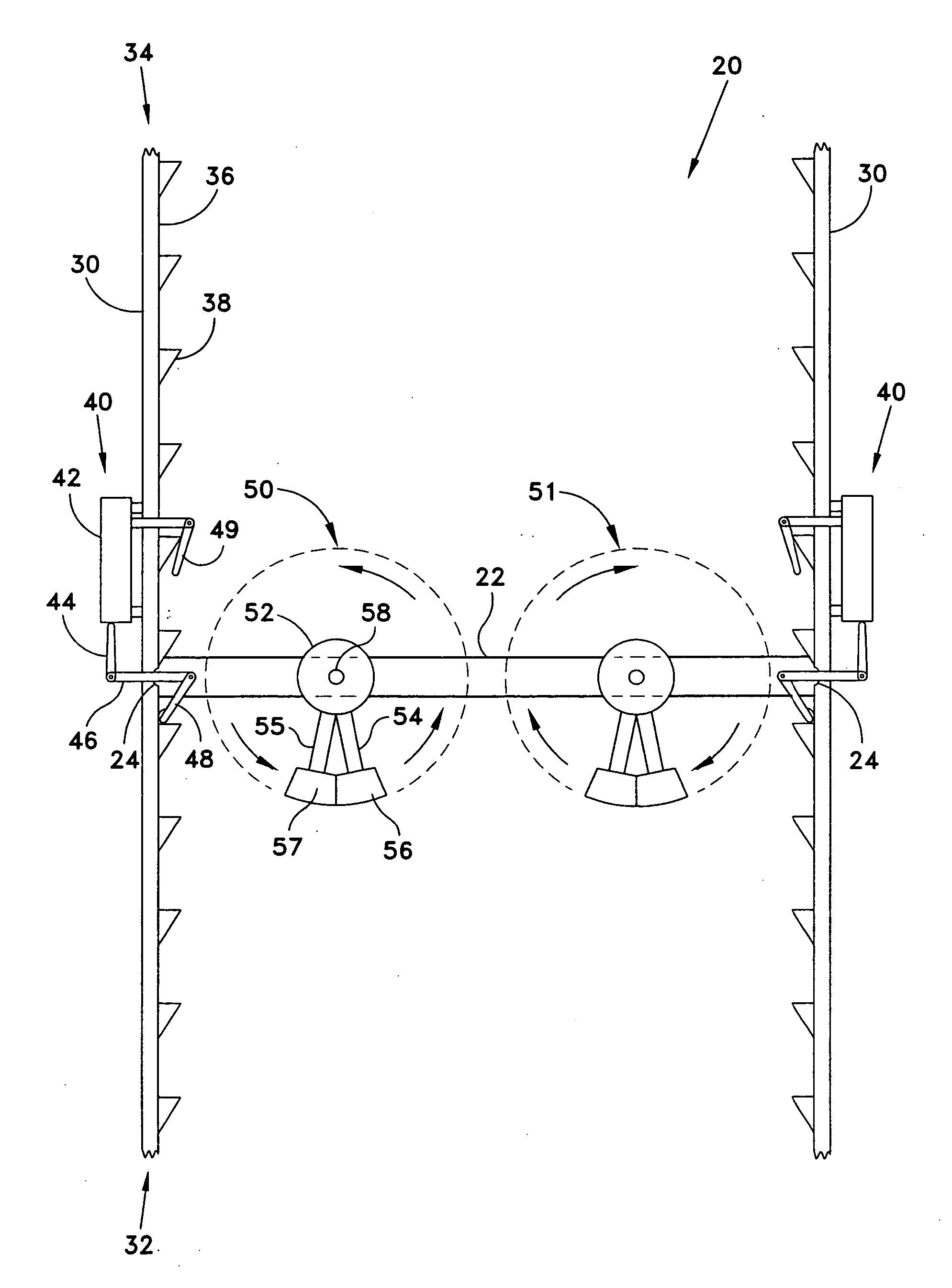
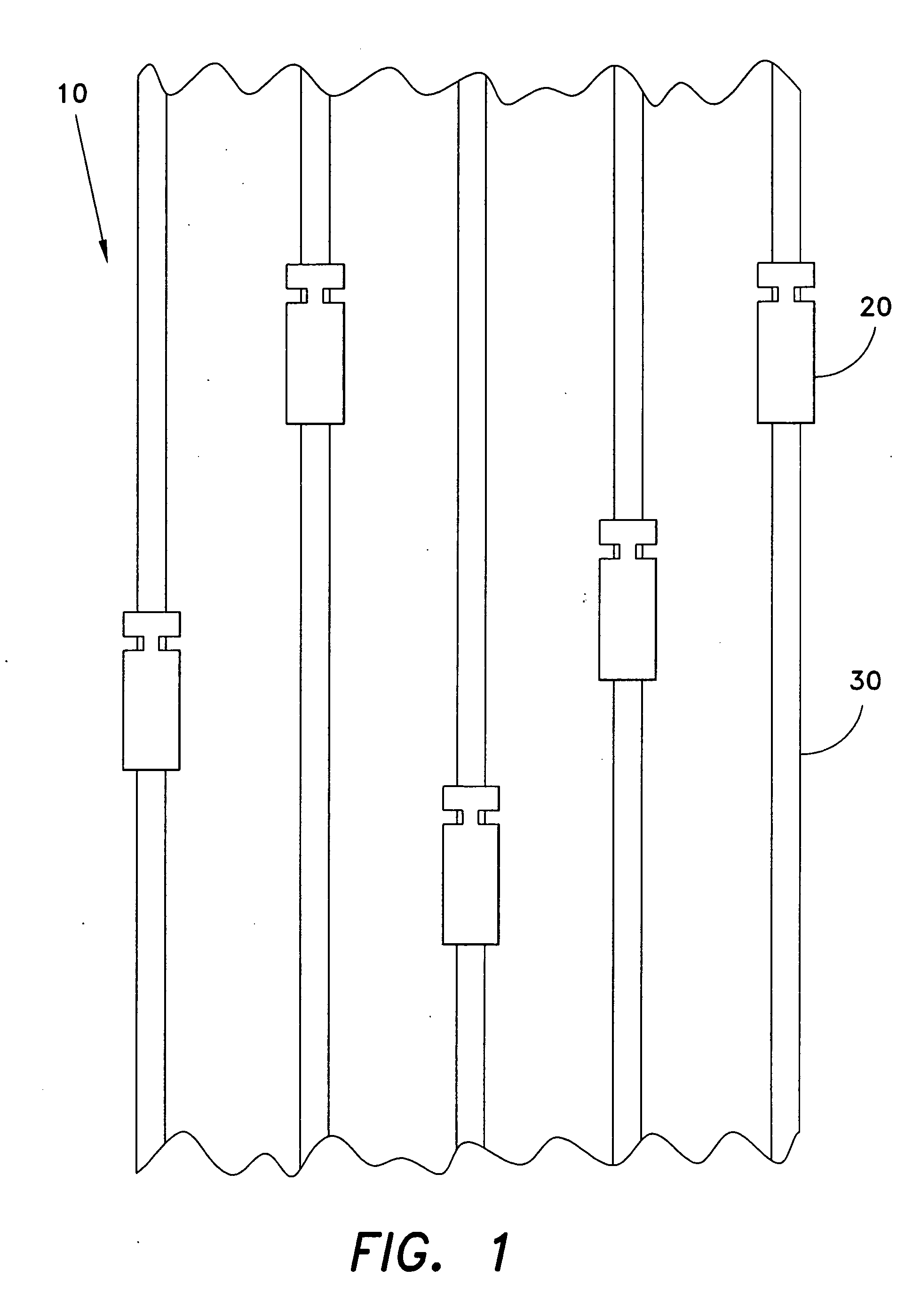
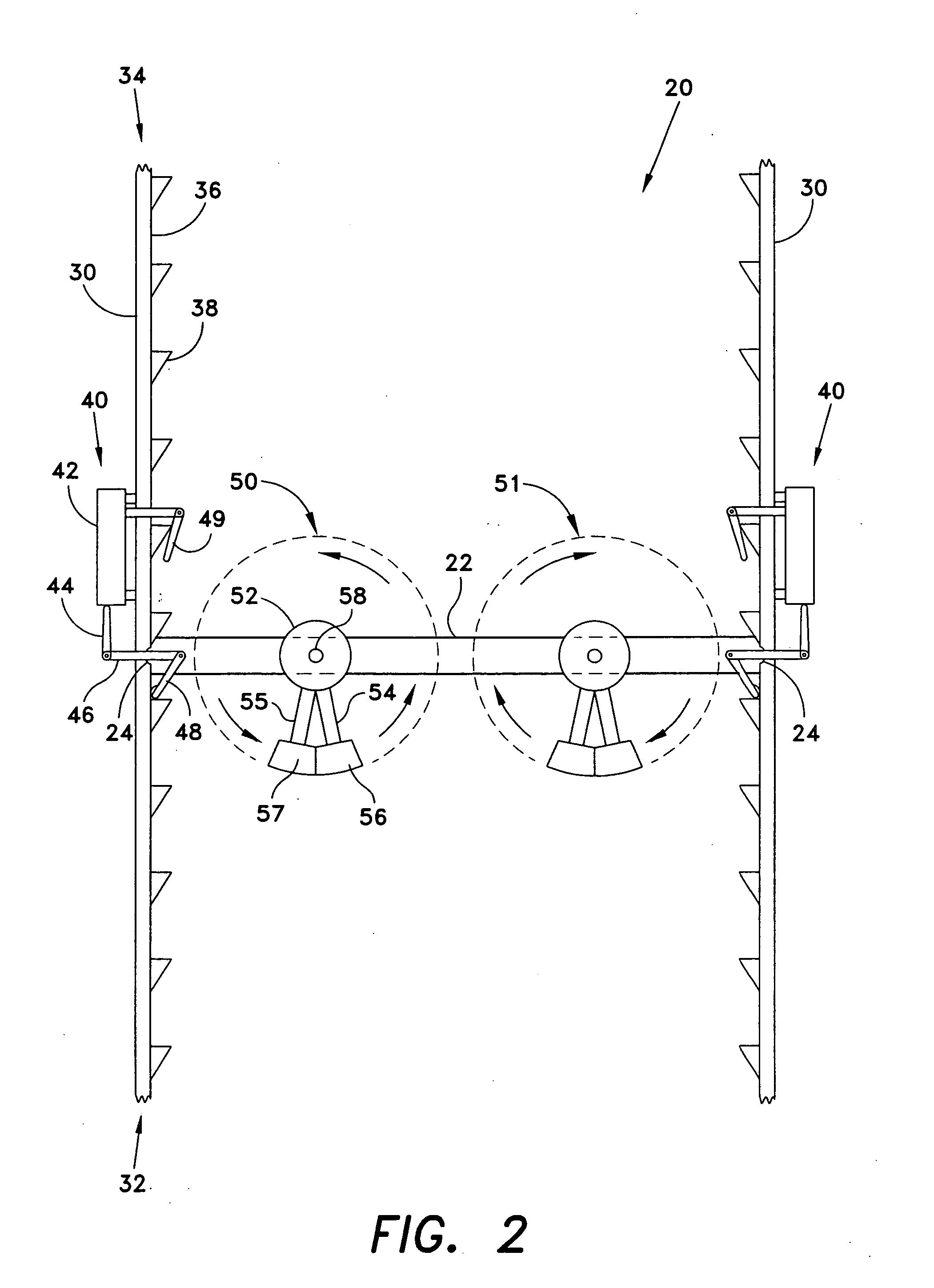
[0032] The present invention is a propulsion device that converts rotational energy into directional, linear energy induced motion. The propulsion device is a mass retentive linear impeller 10 that is used to covert rotational energy into linear thrust for a variety of travel vehicles including, but not limited to, airplanes, spacecraft, seacraft or land vehicles. The mass retentive linear impeller 10 comprises a system of tracks 30, with a plurality of torque carriages 20 and a plurality of actuator assemblies 40 (depicted in FIG. 2). The plurality of torque carriages 20 are slidably attached to the system of tracks 30. The number of torque carriages 20 used is dependent on the desired amount of linear thrust.

[0033]FIG. 2 depicts an interior view of a torque carriage 20. All of the individual torque carriages 20 are configured in the same manner so discussion of only one torque carriage 20 is required. The torque carriage 20 comprises a framework 22, a pair of counter-rotating fly...


PUM


Abstract

A mass retentive linear impeller is used to convert rotational energy into directional, linear energy. The mass retentive linear impeller comprises a plurality of tracks with a plurality of torque carriages located on the tracks. The torque carriages further comprise two counter rotating flywheels, which are located on a framework. Two rotating arms are located inside of the flywheel and are attached to a center motor of the flywheel, which act as a central axis for the rotating arms. A weight is located at the distal end of each rotating arm. The rotating arms induce a centrifugal force, which creates a temporary pull in one direction. This produces a sequence of forward and backward thrusts.

Description

CROSS-REFERENCE TO RELATED APPLICATION [0001] This application claims the benefit of U.S. Provisional Patent Application Ser. No. 60 / 442,908, filed Jan. 28, 2003.BACKGROUND OF THE INVENTION [0002] 1. Field of the Invention [0003] The present invention relates to propulsion devices, and more particularly to a mass retentive linear impeller for converting rotational energy into a linear motion for thrust. [0004] 2. Description of Related Art [0005] Propulsion devices of many kinds are commonly used in many different applications. Propulsion devices such as motors are used every day in automobiles. High velocity propulsion devices such as rockets are used in airplanes, missiles and spacecraft. When a car moves, its motor uses fuel to turn the wheels that act against the road, with the reaction resulting in forward motion. When a rocket moves it expels accelerated mass in the direction opposite to its forward motion. The mass expelled by the rocket is fuel and a rocket uses a large amou...

Claims


Application Information

Patent Timeline
Patent Type & Authority Applications(United States)
IPC IPC(8): F03G3/08F03H99/00F16H27/04
CPCF03G3/08Y10T74/18536F03H99/00F03G7/10F03G7/125
Inventor KEEFE, ALLEN
Owner KEEFE ALLEN
Learn More