Device to switch over a mechanical shifting means

a technology of mechanical shifting and switch means, which is applied in the direction of mechanical control devices, manual control with multiple controlled members, and single controlling member manual control, etc., can solve the problems of limiting the pre-stressing force that can be overcome, causing noise, and only allowing the position “p” to be disengaged, so as to reduce the noise generated and save costs

Inactive Publication Date: 2005-07-28
TELEFLEX AUTOMOTIVE GERMANY
View PDF5 Cites 15 Cited by
  • Summary
  • Abstract
  • Description
  • Claims
  • Application Information

AI Technical Summary

Benefits of technology

[0012] The parking position “P” is held by a spring of the locking magnet, whereby the locking lever is positioned in the parking position P in such a way that the locking groove does not release the radius of motion of the blocking pin and the bell crank is locked without current, and the pull rod or push rod cannot be moved out of the shifting gate. Therefore, the locking magnet then only has to work against the friction torque of the blocking pin of the bell crank in the locking lever. As a result, it is advantageously possible to employ a small magnet that only has to generate small forces (cost savings), thereby also reducing the noise generated. Advantageously, the parking lock can be disengaged via a pulse to the locking magnet, whereby the locking lever can be moved in such a way that the locking groove releases the blocking pin in the direction of motion and the bell crank can be freely moved. By actuating the pull rod or push rod, it is then possible to shift between the positions R, N and D in the shifting gate.

Problems solved by technology

The parking position “P”, however, can only be disengaged when the brake pedal is depressed and when the on-board electrical system is being supplied with power.
These mechanisms, however, limit the pre-stressing forces that can be overcome and they also give rise to noise.

Method used


Image

  • Device to switch over a mechanical shifting means
  • Device to switch over a mechanical shifting means
  • Device to switch over a mechanical shifting means

Examples


Embodiment Construction

[0022] The device according to the invention makes use of a triple lever transmission, thus reducing the effective pre-stressing force exerted on the locking magnet.

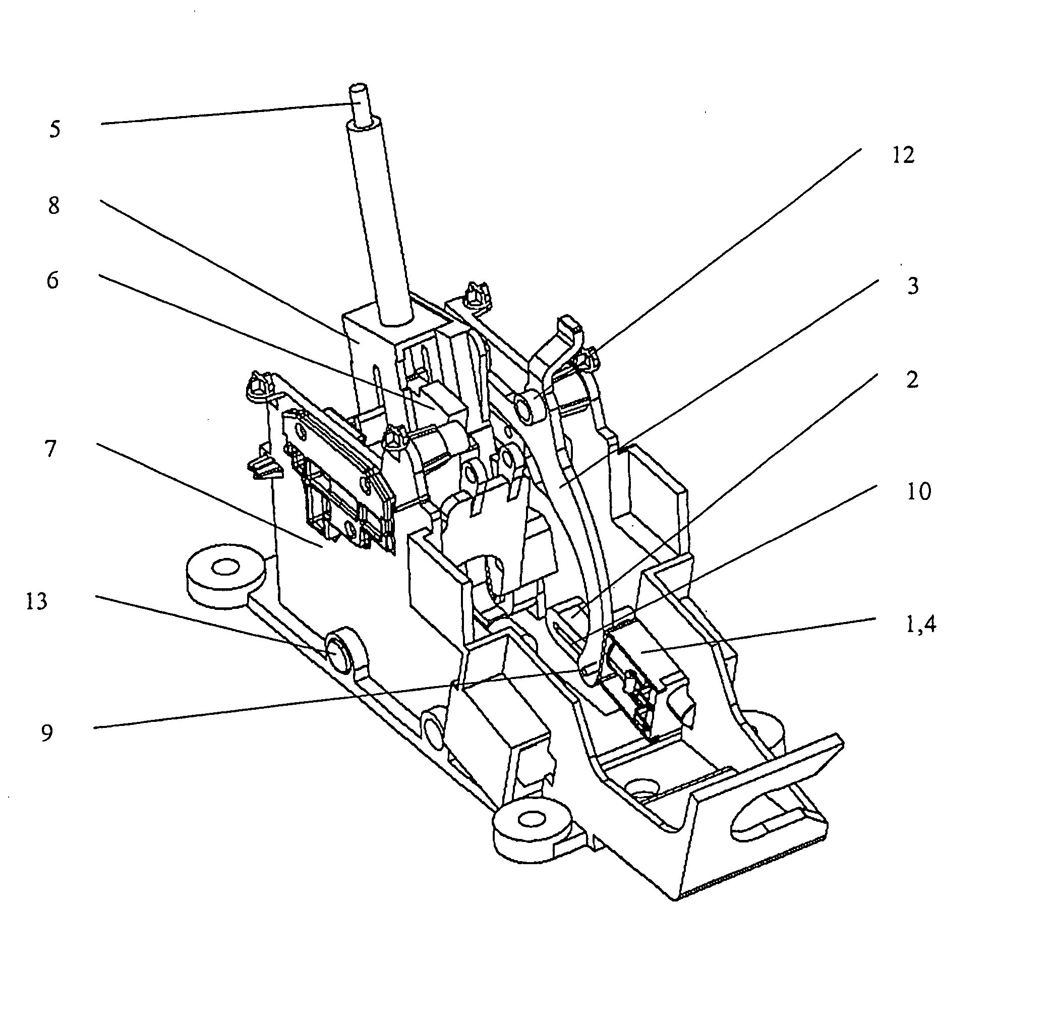
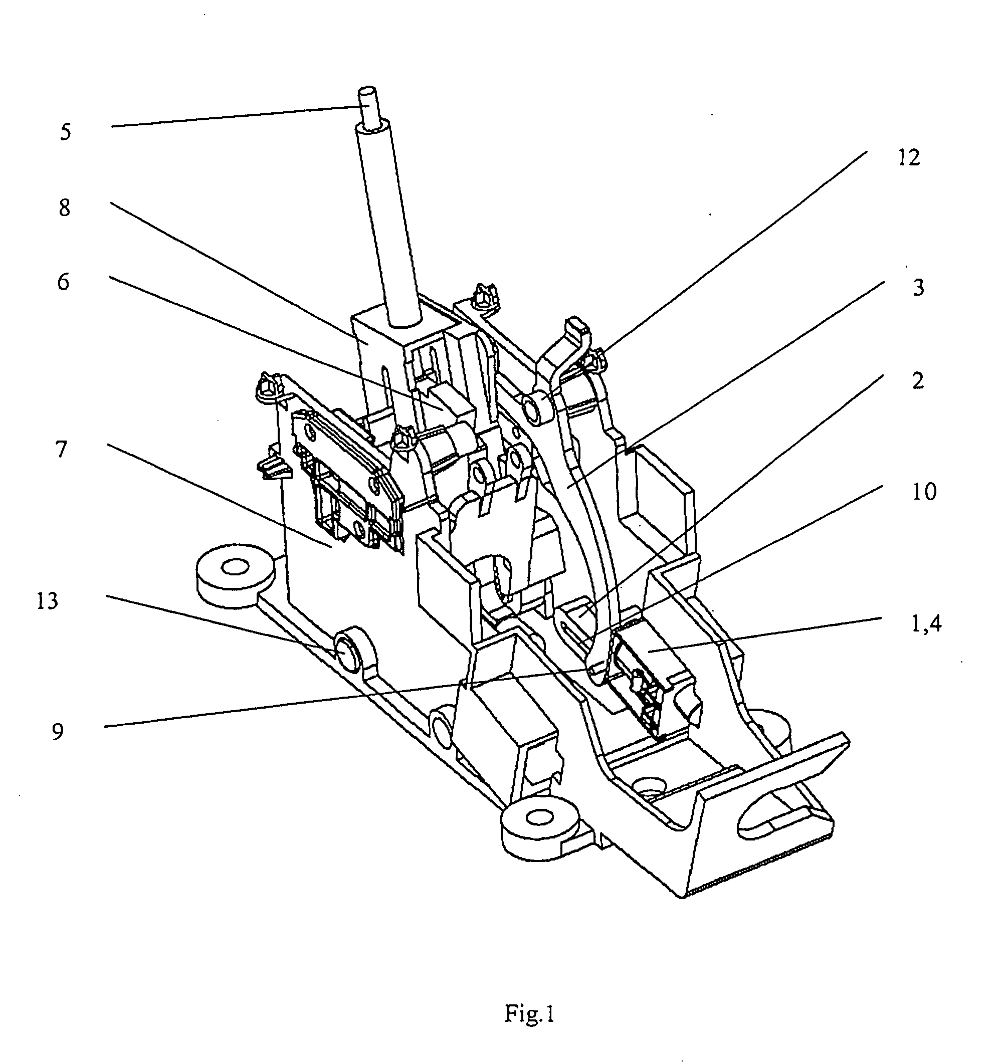
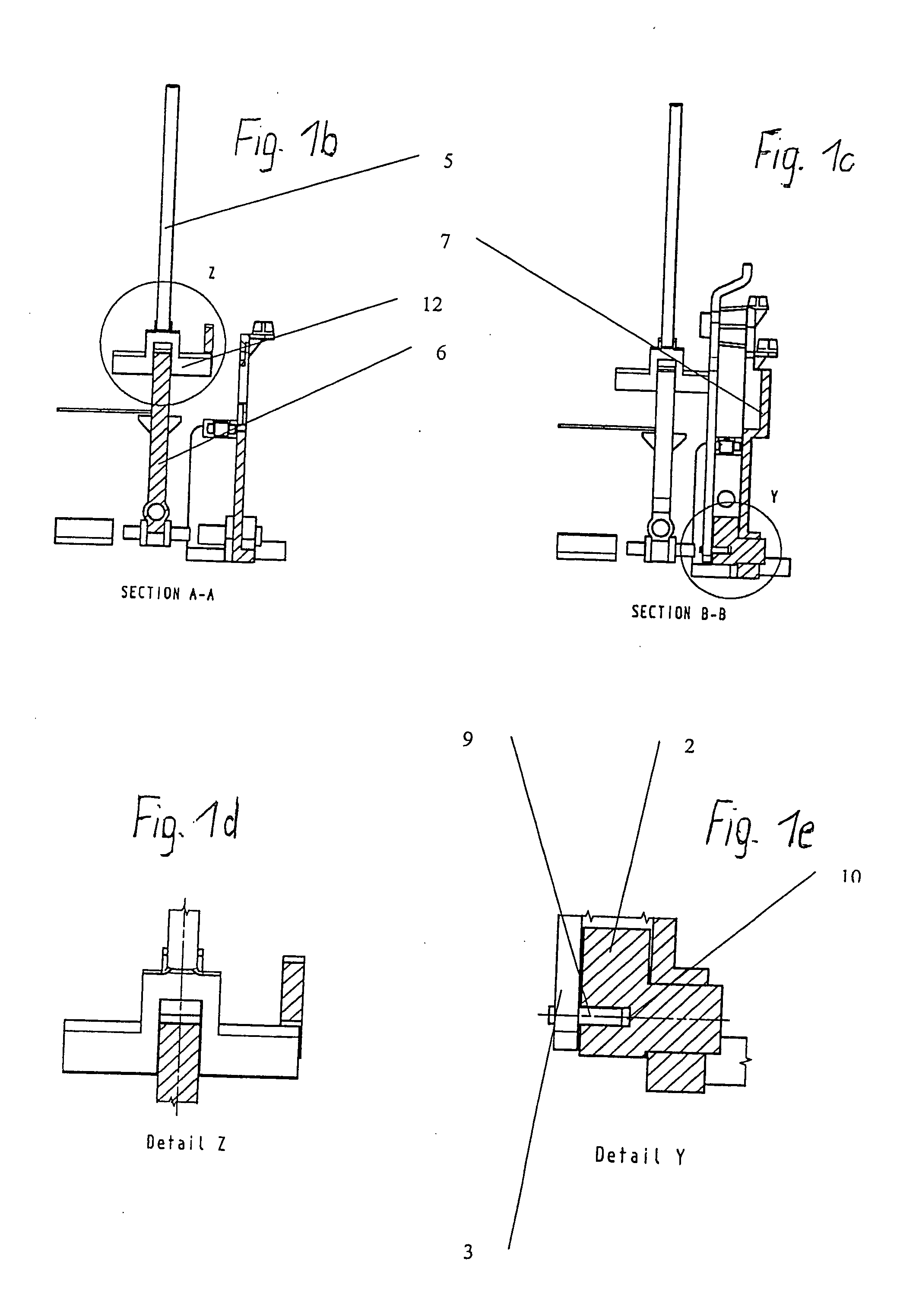
[0023] In FIG. 1, the device according to the invention is shown in the installed state in a housing 7 inside an automatic transmission. Here, manual shift gear lever 8 having a connecting rod 5, in this case a pull rod can be actuated in order to shift between the individual positions R, N, D and P in the shifting gate 6 of the automatic transmission. For this purpose, the pull rod 5 is fitted with a link slide 14 that extends in a U-shaped or bridge-like manner over the shifting gate 6, whereby a bell crank 3 lies on a lateral bracket of the U-shaped or bridge-like link slide 14 (FIGS. 1b and 1d).

[0024] Here, the bell crank 3, having axis of rotation 12, is arranged so as to achieve a reduction of the pull rod 5 relative to the blocking pin 9. The locking lever 2 has a locking groove 10 in which the blocking pin of t...


PUM


Abstract

A device to switch over a mechanical shifting means between at least two shifting states, particularly for purposes of switching on and off a parking lock of an external selector for an automatic transmission, whereby a shifting gate that can be actuated via a shift gear lever having a connecting rod such as a pull rod or push rod is arranged in a housing and the parking position is held by a locking magnet, whereby a locking lever having an axis of rotation is provided inside the housing, said lever interacting with the locking magnet, whereby the locking lever is connected via a bell crank having a blocking pin and having an axis of rotation to the pull rod or push rod having an axis of rotation, and to a link slide that can be moved relative to a shifting gate.

Description

[0001] Priority is claimed to German Patent Application No. DE 103 61 209.2, filed on Dec. 24, 2003, the entire disclosure of which is incorporated by reference herein. [0002] The invention relates to a device to switch over a mechanical shifting means between at least two shifting states, particularly for purposes of switching on and off a parking lock of an external selector for an automatic transmission. BACKGROUND [0003] Automatic transmissions equipped with mechanical parking locks are known from the state of the start. [0004] A conventional automatic transmission for motor vehicles usually comprises at least four operating modes, corresponding to the shifting positions “P”, “R”, “N” and “D” on the gearshift lever. As is known, “R” stands for reverse, “D” for drive and “N” for neutral, in which the engine and the wheels are mechanically disengaged. [0005]“P” stands for “park”, a state in which the gear is mechanically locked by a parking lock against the transmission of movemen...

Claims


Application Information

Patent Timeline
Patent Type & Authority Applications(United States)
IPC IPC(8): B60K20/02F16H59/10F16H61/22F16H63/38
CPCF16H59/10Y10T74/20018F16H61/22
Inventor BUERGER, ARNDGROSSMANN, STEPHANBAUERFEIND, GERALD
Owner TELEFLEX AUTOMOTIVE GERMANY
Why Eureka
Try Eureka