

Gripping or clamping mechanisms
- Summary
- Abstract
- Description
- Claims
- Application Information
AI Technical Summary
Benefits of technology
Problems solved by technology
Method used
Image

Examples
Embodiment Construction
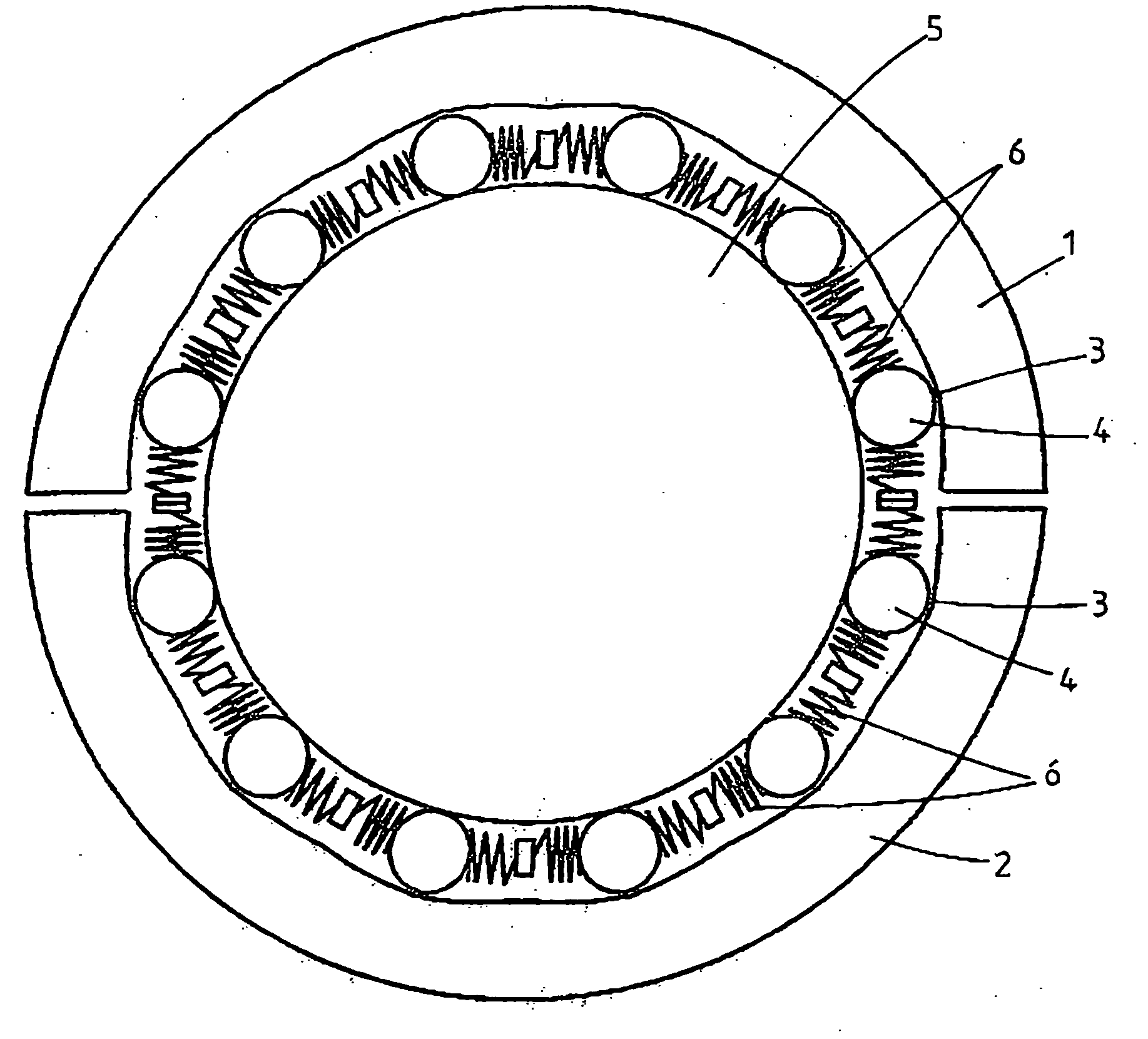
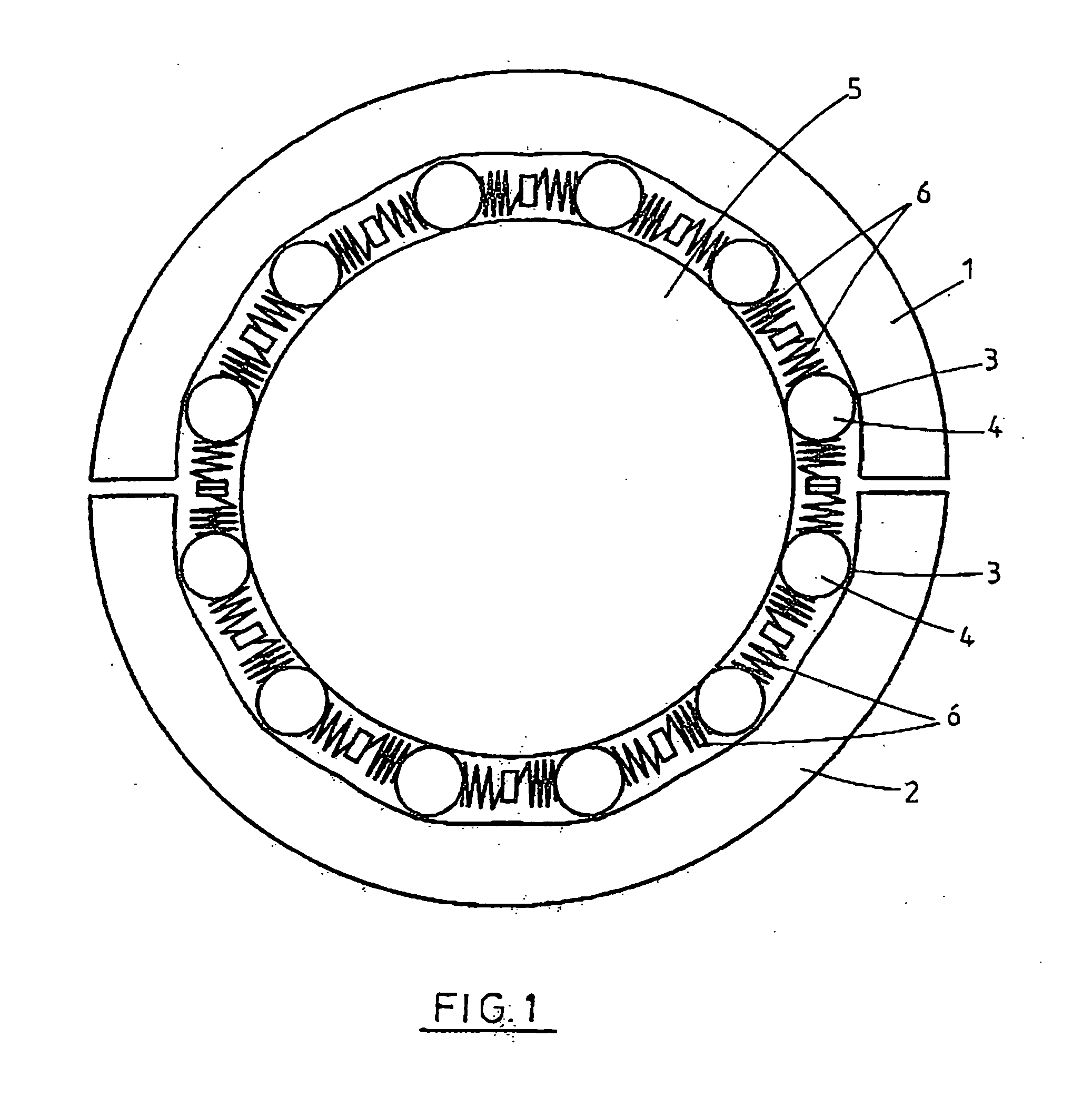
[0089]FIGS. 1 and 2 illustrate the concept of the clamping mechanism of the invention. Jaws 1 and 2 are provided with wedge shaped recesses 3 having rollers 4 positioned therein. Jaws 1 and 2 may be moved apart so that a tubular member 5 may be moved laterally into the jaws. Jaws 1 and 2 may be pivotally connected together at one end to enable the jaws to open and close or the jaws may be translated apart and forced back together. Although two jaws are shown in FIG. 1 it will be appreciated that 3 or more jaw segments could be used.
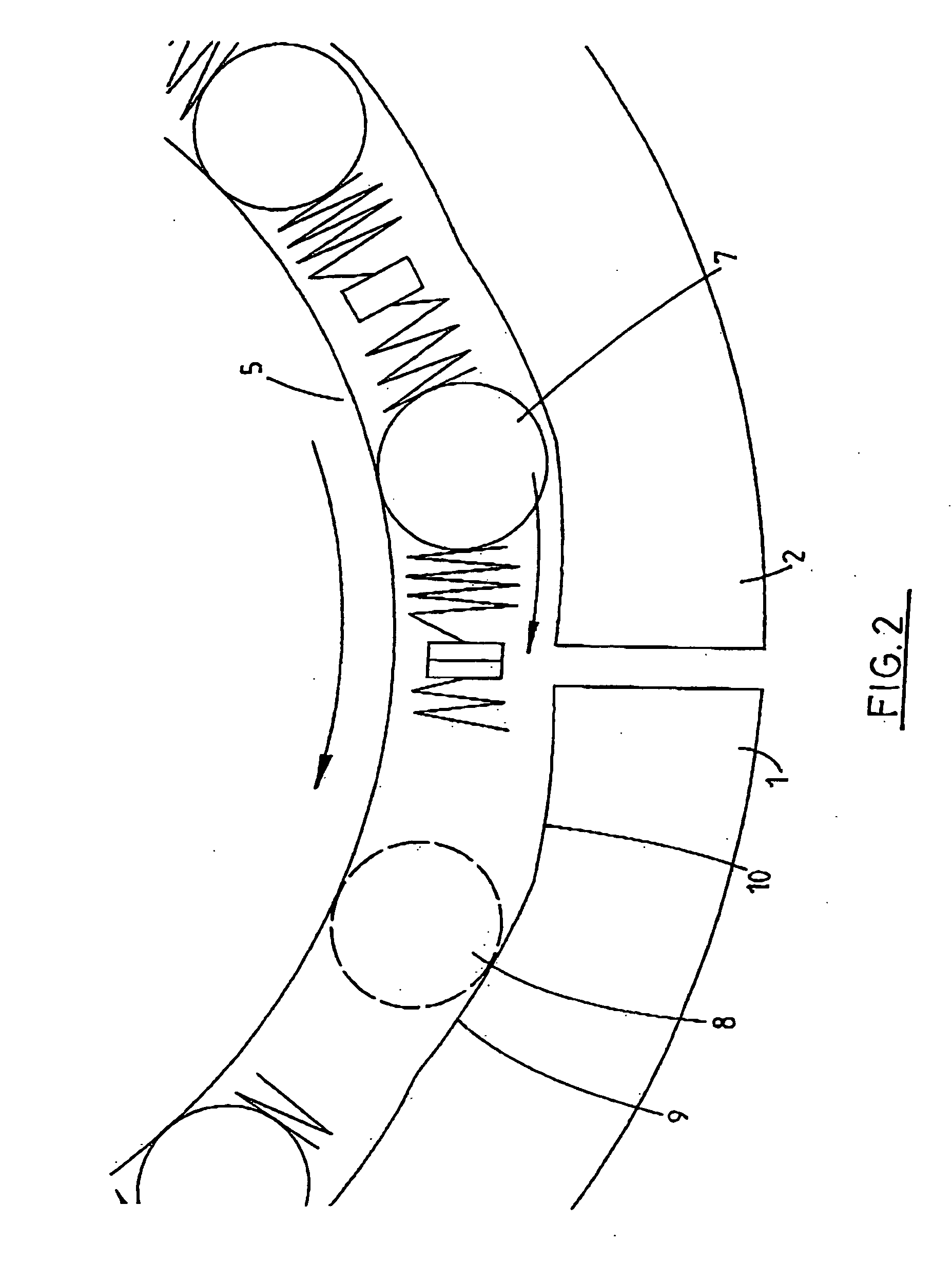
[0090] Rollers 4 are biased apart by springs 6. When jaws 1 and 2 are closed around a tubular member 5, as shown in FIG. 1, rollers 4 are initially located at the apex of recess 3 (see roller 7 in FIG. 2). When the tubular member 5 is rotated rollers 4 are urged by tubular member 5 in the direction of rotation of tubular 5.
[0091] The dashed roller 8 in FIG. 2 illustrates the position adopted by the roller when urged to the left by rotation of tubular me...
PUM
 Abstract
Description
Claims
Application Information