Heat-dissipating device

a heat dissipation device and heat dissipation technology, which is applied in the direction of semiconductor devices, cooling/ventilation/heating modifications, basic electric elements, etc., can solve the problems of affecting the heat dissipation effect of the heat-conductive base plate 151, the heat-dissipation center is relatively poor, and the heat-dissipation performance is not at its best performance of heat-dissipation, etc., to reduce the working noise probability heat dissi heat dissipating device and heat dissipating device and heat dissip heat dissipating performance and heat dissipating performance and other problems, which is applied in the field of heat dissipating performance performance and the a heat dissipation device technology of heat dissipating device and heat dissipating device and heat dissipating device technology, applied in the field of heat dissipating device and heat dissipating device and heat diss

Active Publication Date: 2005-07-28
GIGA BYTE TECH CO LTD
View PDF10 Cites 31 Cited by
  • Summary
  • Abstract
  • Description
  • Claims
  • Application Information

AI Technical Summary

Benefits of technology

[0010] Accordingly, how to design a novel heat-dissipating device allowed for uniformly blowing the cooling airflow toward each of the fins and decreasing the probability of collision between the cooling airflow and the fins in order to achieve the effectively raised heat-dissipating performance and the reduced working noise is the key point of the present invention.
[0011] It is a primary object of the present invention to provide a heat-dissipating device capable of eliminating the imperfection in technology with which the conventional heat-dissipating device is confronted.
[0012] It is a secondary object of the present invention to provide a heat-dissipating device provided with a cross-flow type fan disposed within an accommodating opening formed by fins such that a cooling airflow generated by the cross-flow fan may be uniformly blow toward everywhere of each of the fins in order for achieving the effectively raised performance of heat-dissipation.
[0013] It is another object of the present invention to provide a heat-dissipating device used with a cross-flow type fan for generating an approximately parallel cooling airflow with respect to fins in such a way that the probability of the collision between the cooling airflow and the fins may be effectively reduced so as to lower the working noise.
[0014] It is still another object of the present invention to provide a heat-dissipating device used for achieving the best performance of heat-dissipation by means of at least one heat-conductive pipe contacting with the center of a heat-conductive base plate, and facilitating the removal of the high working temperature at the center of the heat-conductive base plate.

Problems solved by technology

As such, not only degraded performance resulted from a hindered or degraded airflow, but also annoying working noise may emerge.
Moreover, the effect of heat-dissipation at the center of the heat-conductive base plate 151 is relatively poor and thus unattainable to its best performance of heat-dissipation, owing to the motor 117, which must be disposed at the center of the fan 11, and the formed spiral airflow.
This may also significantly degrade the best performance of heat-dissipation.
It is still hard for the cooling airflow to arrive at the remote fins or the heat-conductive base plate, due to the fact that the fan is disposed at either the top end or the side end of the fins, so as to significantly degrade the best heat-conductive performance.
The spiral airflow may still hit against the fins because the axial-flow type fan is used, which results in not only degrading heat-conductive performance, but also generating annoying working noise.
The center of the axial-flow type fan is still not supplied with the cooling airflow, leading to degrading the best performance of heat-dissipation.

Method used


Image

  • Heat-dissipating device
  • Heat-dissipating device
  • Heat-dissipating device

Examples


Embodiment Construction

[0023] The structural features and the effects to be achieved may further be understood and appreciated by reference to the presently preferred embodiments together with the detailed description.

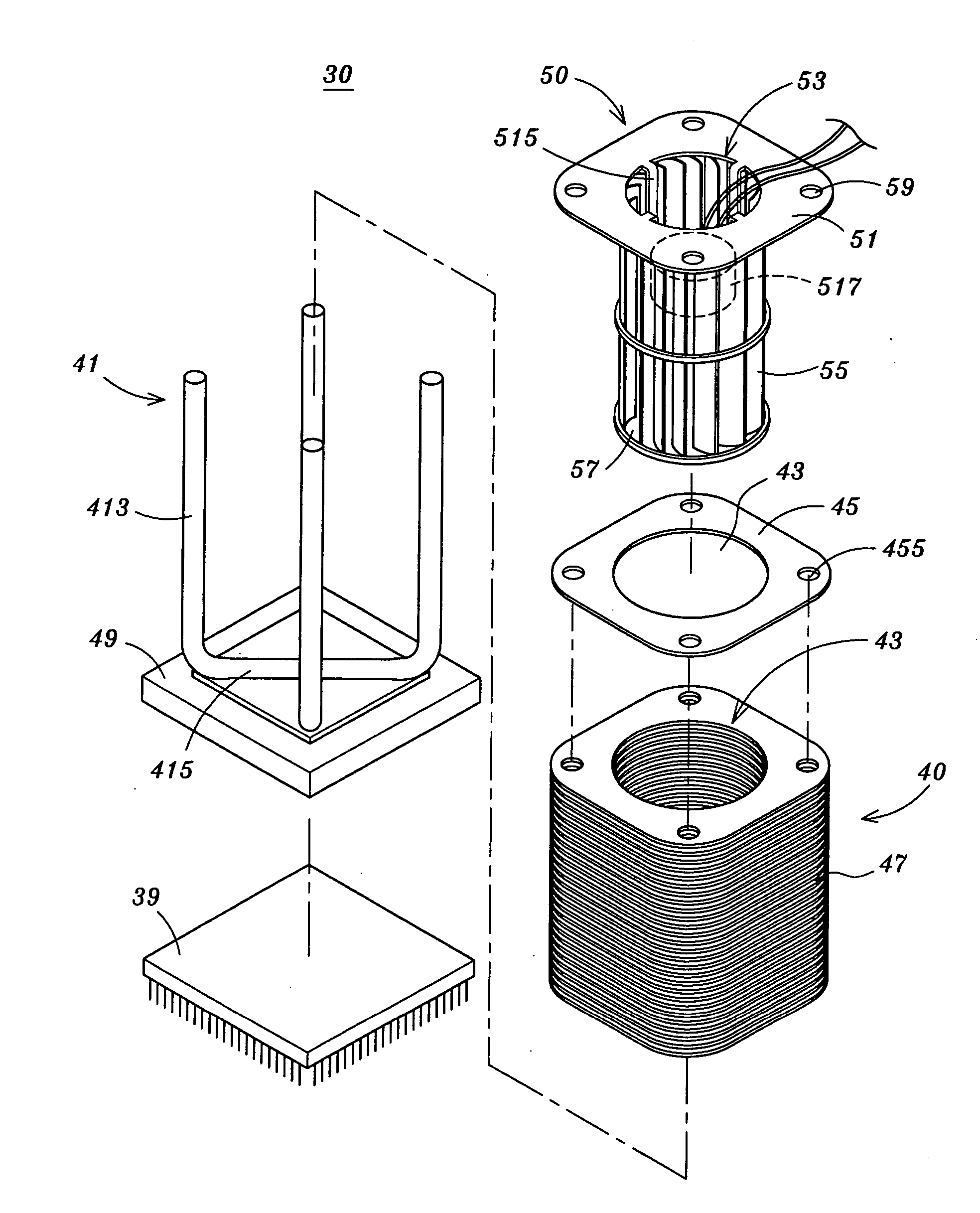
[0024] Referring to FIG. 3, firstly, there is shown a structural disassembled diagram of a heat-dissipating device according to one preferred embodiment of the present invention. As shown in this figure, a heat-dissipating device 30 of the present invention mainly comprises a radiator 40 and a cross-flow type fan (centrifugal fan) 50. In this case, the radiator 40 is provided with at least one heat-conductive pipe 41, for example, a U-shaped heat-conductive pipe in this embodiment, may be attached to a heat-conductive base plate 49. A bottom pipe 415 of this heat-conductive pipe is horizontally disposed at the center of the heat-conductive base plate 49 in a staggered manner, and whereby, the high working temperature of the heat-conductive base plate 49 attached to the surface of various el...


PUM


Abstract

A heat-dissipating device is provided. The heat-dissipating device is capable of cooperating a cross-flow type fan, mainly comprising a heat-conductive base plate attached with at least one heat-conductive pipe, and fixedly provided with a plurality of fins on the heat-conductive pipe. An air-outlet gap is naturally formed between any two of the adjacent fins, and an accommodating opening is disposed at an identical location on each of said fins. Within the accommodating opening, a cross-flow type fan is further presented. When fan blades of the cross-flow type fan rotating, an airflow thus generated is allowed for uniformly contacting with each of said fins and discharged through said air-outlet gaps. Thereby, not only the significantly raised effect of heat-dissipation of the heat-conductive base plate, but also the effectively reduced working noise due to a parallel path of the airflow with respect to the fins may be obtained.

Description

FIELD OF THE INVENTION [0001] The present invention is related to a heat-dissipating device, particularly to a heat-dissipating device capable of cooperating with a cross-flow type fan, by which the significantly raised effect of heat-dissipation of a heat-conductive base plate. BACKGROUND [0002] Accordingly, as the semi-conductor process progresses increasingly, the volume of the chip and processor used in current electronic apparatuses or computer systems, such as central processing units (CPUs) and another electronic devices in the computer systems, may become smaller and smaller, whereas the working performance and the computation speed is relatively doubled. Due to the accelerated data processing speed, the accompanying working temperature may be just raised without dropping. Therefore, for the purpose of avoiding the degraded computation efficiency and even the damage resulted from the super-high working temperature, the heat-dissipating device is required for the CPUs and ano...

Claims


Application Information

Patent Timeline
Patent Type & Authority Applications(United States)
IPC IPC(8): F28D15/02H01L23/427H01L23/467H05K7/20
CPCH01L23/427H01L23/467H01L2924/0002H01L2924/00
Inventor MA, MOU-MINGTSENG, HSIANG-CHIEHLEE, TUNG-SHANLIU, YI-SONGCHOU, CHIA-MIN
Owner GIGA BYTE TECH CO LTD
Why Eureka
Try Eureka