Displacement filter apparatus and method

a filter and displacement technology, applied in the direction of filtration separation, sedimentation settling tanks, separation processes, etc., can solve the problems of large and costly support frames and hydraulic systems, ineffective filtering methods, and inability to pass through liquid, etc., to reduce the time necessary, simplify and cost-effective, and the effect of less costly

Inactive Publication Date: 2005-07-28
DUBY SEAN R
View PDF48 Cites 24 Cited by
  • Summary
  • Abstract
  • Description
  • Claims
  • Application Information

AI Technical Summary

Benefits of technology

[0010] Advantageously, preferred embodiments and methods utilize a displacement principle for filtering slurries having a relatively high concentration of solids without the above-described disadvantages associated with the filter press. Preferred embodiments utilize a simplified structural arrangement to permit a less costly support structure and closure system to be provided. In addition, preferred embodiments drastically reduce the time necessary for discharging particulate matter and preparing the filter for subsequent use. Furthermore, preferred embodiments are desirably capable of being equipped with simplified and cost-effective automated cleaning systems to preferably completely eliminate the need for an operator and further reduce the down-time of the filter apparatus.

Problems solved by technology

However, with this type of filtering process, once the surface of the filter element is substantially covered with solid particulate matter, liquid is no longer able to pass through.
However, this method of filtering is inefficient because the tube press only processes a fixed volume of slurry during a filtering cycle.
However, due to the large forces generated by the pressure within the spaces, a large and costly support frame and hydraulic system is necessary to hold the plates together during the filter cycle.
Because as many as a hundred or more individual plates may be used, the cleaning process is very time-consuming and results in excessive down-time in which the filter press is not utilized.
Also, due to the provision of multiple plates, which must be separated from one another to allow the particulate matter to be discharged and the filter media to be cleaned, fully automated filtering systems are often prohibitively expensive.

Method used


Image

  • Displacement filter apparatus and method
  • Displacement filter apparatus and method
  • Displacement filter apparatus and method

Examples


Embodiment Construction

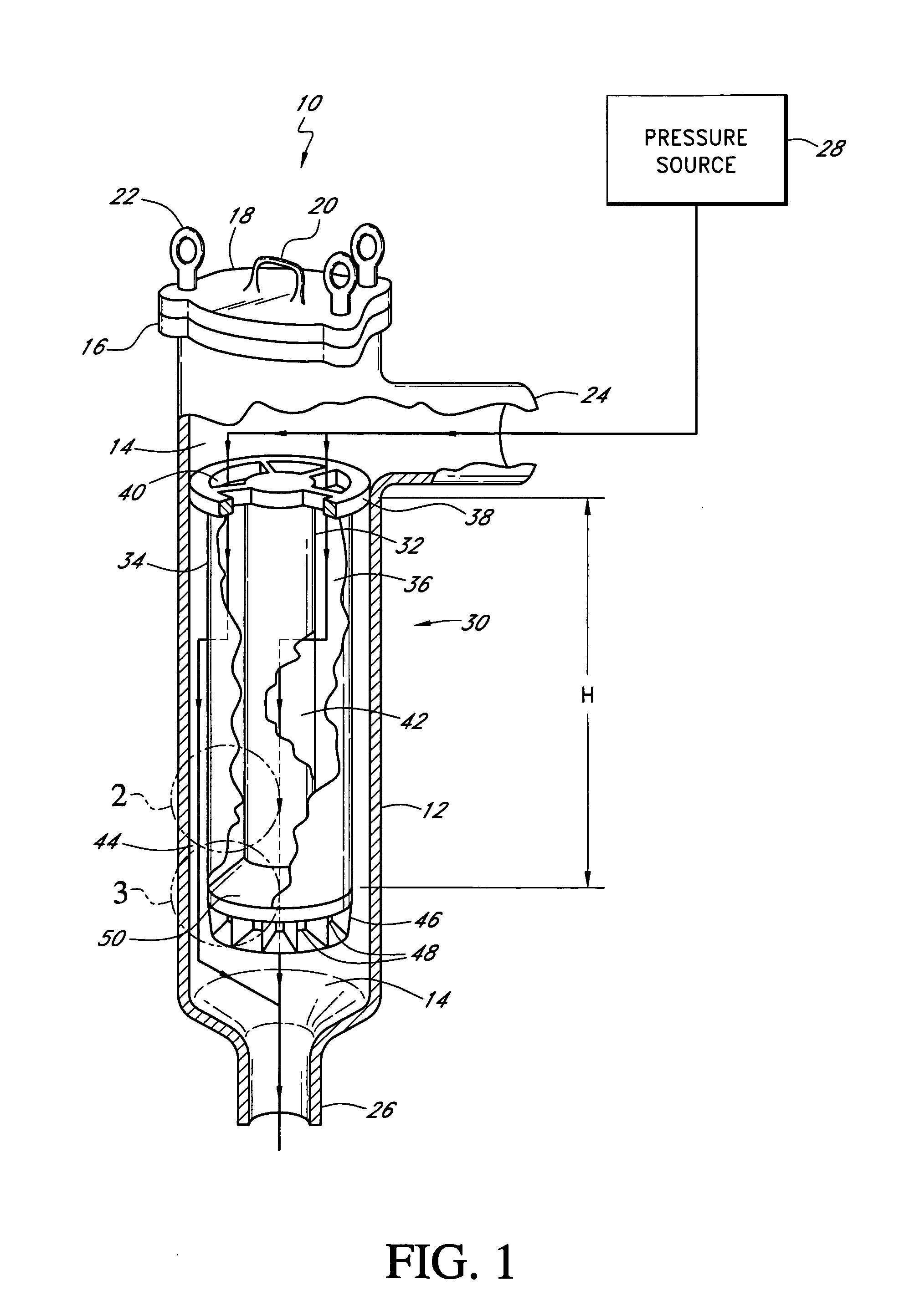
[0045]FIGS. 1-3 illustrate a preferred embodiment of a filter apparatus 10, generally referred to as a “filter” herein. The filter 10 includes a substantially tube-shaped vessel 12 that defines an enclosed space, generally referred to by the reference numeral 14. The upper, open end of the vessel 12 terminates in a flange 16, which extends generally perpendicular to the wall of the vessel 12. A closure, or lid 18, preferably rests on the flange 16 to close the upper end of the vessel 12. The lid 18 may include a handle 20 to allow the lid 18 to be easily removed. Desirably, the lid 18 is capable of being secured to the vessel 12 so as to form a fluid tight seal. In the illustrated embodiment, a number of threaded fasteners, such as eyebolts 22, secure the lid 18 to the flange portion 16 of the vessel 12. However, other suitable means of attachment may also be used, such as other mechanical or hydraulic means. In addition, other suitable methods of closing the vessel 12 may be utiliz...


PUM


Abstract

A method and apparatus for filtering a slurry utilizing a displacement filtering principle. The filter apparatus desirably includes an inner filter and an outer filter. Both the inner and outer filters are preferably substantially annular in shape and positioned concentrically with respect to each other. A particulate collection volume is at least partially defined between the inner and outer filter. The method includes directing a flow of slurry into the particulate collection volume under sufficient pressure to force fluid within the particulate collection volume through one of the inner and outer filters and any particulate matter blocking a filtering surface of the inner and outer filters.

Description

RELATED APPLICATION [0001] This application is a continuation of U.S. patent application Ser. No. 10 / 147,230, filed May 15, 2002, the entirety of which is hereby incorporated by reference herein and made a part of the present disclosure.BACKGROUND OF THE INVENTION [0002] 1. Field of the Invention [0003] The present invention relates to the filtering of particulate matter from a slurry. More specifically, the present invention relates to the filtering of slurries having a relatively high particulate content utilizing a displacement filtering principle. [0004] 2. Description of the Related Art [0005] Separating the liquid and solid components of a liquid-solid mixture, or slurry, is a necessary or desirable process in many industries. In many filtering applications, the slurry is a waste product and it is desirable to separate the solid and liquid matter and dispose of them separately. Often, the solid component may be a hazardous material and the liquid component may be reused or rec...

Claims


Application Information

Patent Timeline
Patent Type & Authority Applications(United States)
IPC IPC(8): B01D25/26B01D29/15B01D29/21B01D29/39B01D35/12
CPCB01D25/26B01D29/15B01D29/21B01D29/395B01D35/12B01D25/285B01D29/23B01D29/54B01D29/60B01D29/6438B01D29/6484B01D29/66B01D29/70B01D29/822B01D29/232B01D29/925B01D35/16
Inventor DUBY, SEAN R.
Owner DUBY SEAN R
Why Eureka
Try Eureka