
Photodetector

a technology of photodetector and illuminance sensor, which is applied in the direction of optical radiation measurement, instruments for comonautical navigation, instruments, etc., can solve the problems of lowering the quality of appearance and unable to achieve desired directional characteristics, and achieve the effect of improving the precision of positioning of the light shield part and the photosensitive element of the illuminance sensor

Inactive Publication Date: 2005-07-28
DENSO CORP
View PDF4 Cites 19 Cited by
  • Summary
  • Abstract
  • Description
  • Claims
  • Application Information

AI Technical Summary

Benefits of technology

[0011] Therefore, the mounting space can be reduced more than the case where the solar radiation sensor and the illuminance sensor are provided separately from each other in the instrument panel of a vehicle. Since the sensors are formed in a single package, the number of parts and the number of processes of attachment to a vehicle can be also reduced.
[0028] In particular, according to a twelfth aspect, when the recess is preliminarily formed in a shape according to at least part of the light shielding part in the top face of the transparent resin in correspondence with the position where the light shielding part is positioned, at least part of the light shielding part is fit in the recess formed in the transparent resin, thereby performing position. Thus, precision of positioning of the light shield part with respect to the photosensitive element for a solar radiation sensor and the photosensitive element for an illuminance sensor can improve.

Problems solved by technology

Consequently, the sensor mounting space in the instrument panel becomes larger as compared with the case where only the solar radiation sensor is mounted, thereby lowering the quality of the appearance.
Therefore, in the case where the sensors are arranged in the same package, desired directional characteristics may not be assured.

Method used


Image

  • Photodetector
  • Photodetector
  • Photodetector

Examples


first embodiment

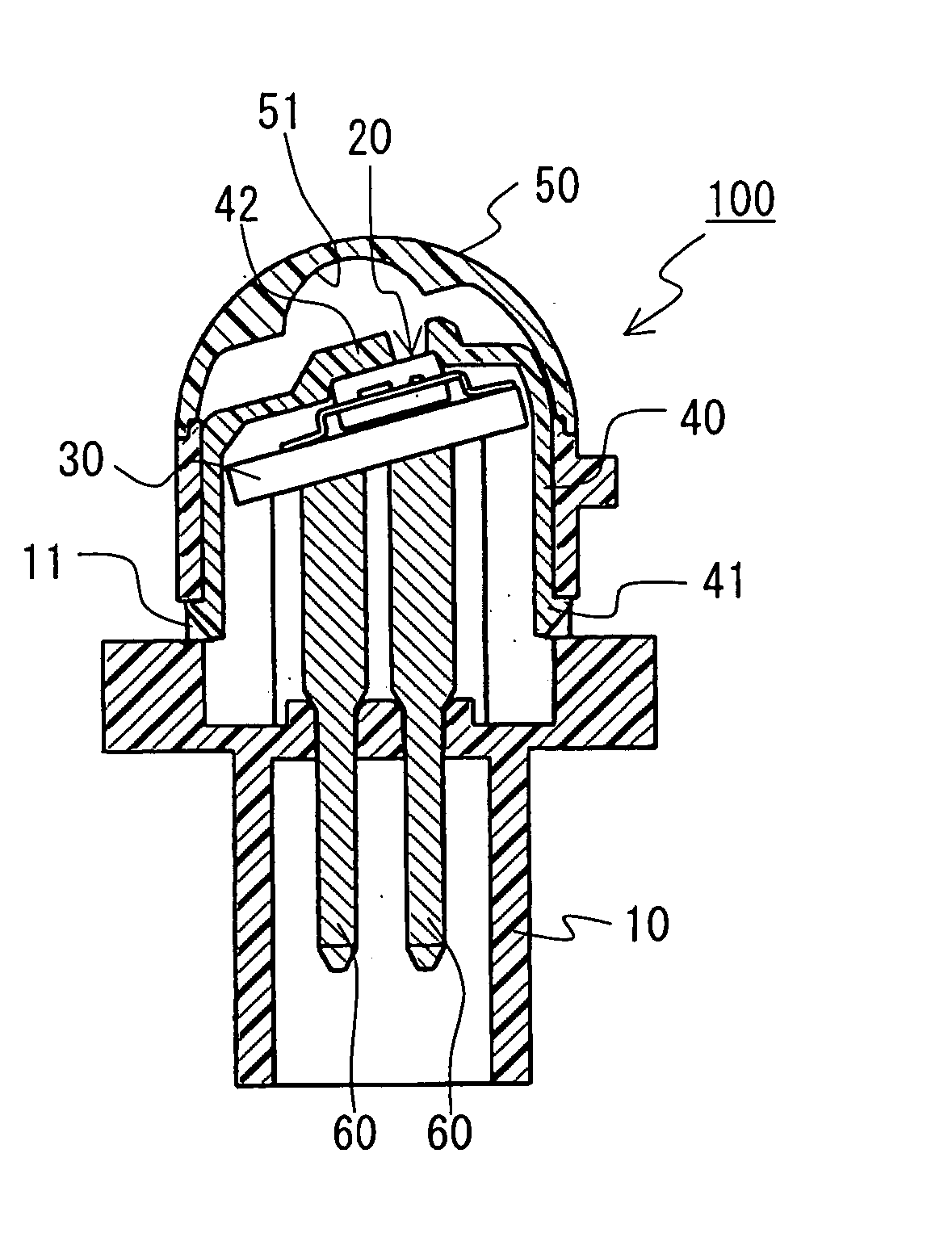
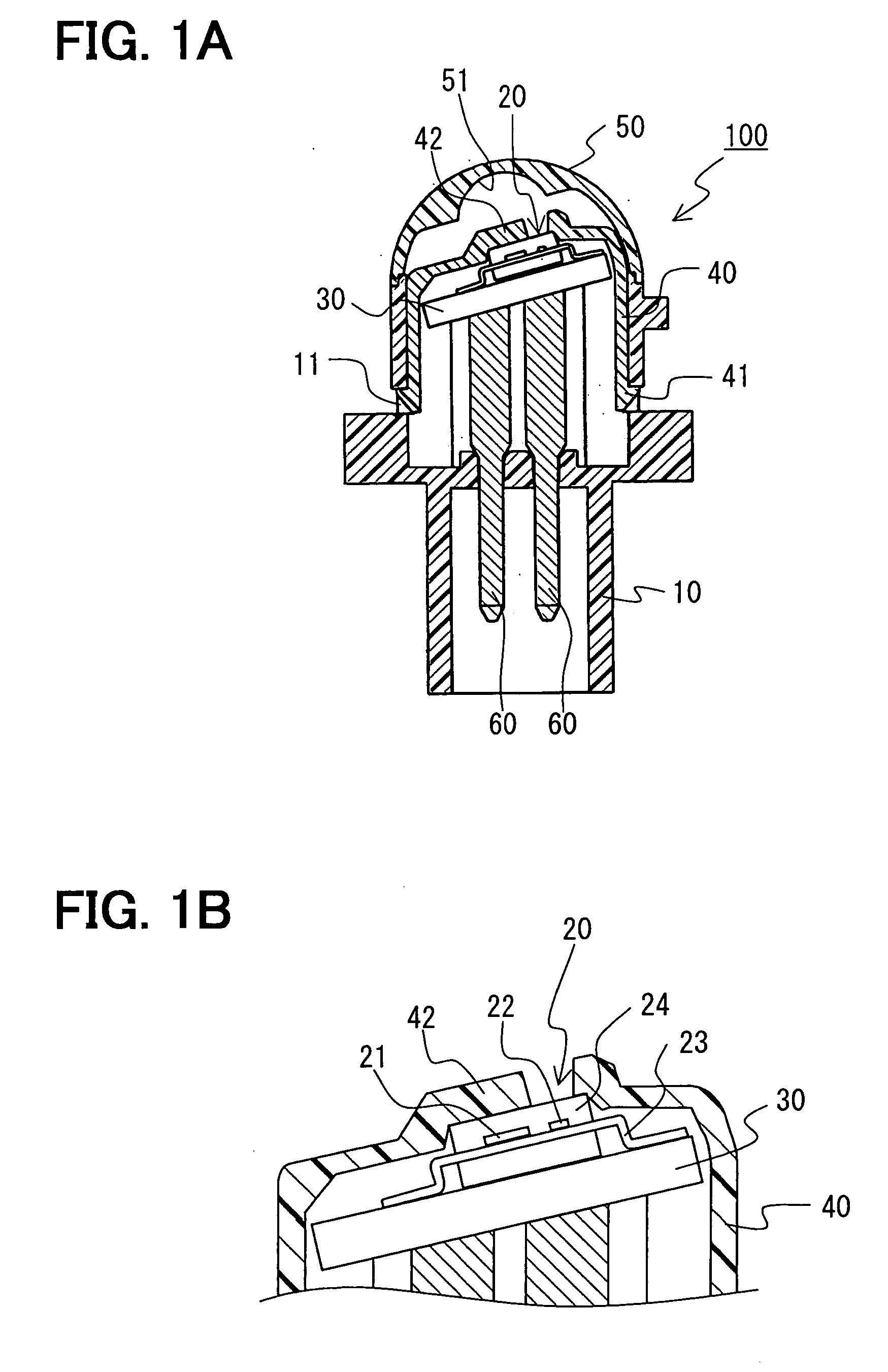
[0038]FIGS. 1A and 1B are diagrams showing a schematic configuration of a photodetector according to a first embodiment. FIG. 1A is a sectional side view and a FIG. 1B is an enlarged cross section of a portion of a photosensitive element. In FIGS. 1A and 1B, a photosensitive element for a solar radiation sensor and a photosensitive element for an illuminance sensor are shown in the same section for ease of illustration.

[0039] As shown in FIG. 1A, a photodetector 100 has a case 10 also equipped with a connector, a light sensor 20, a circuit board 30 of the light sensor 20, a light shielding member 40 for regulating light incident on the light sensor 20, an optical lens 50 as a cap, and terminals 60.

[0040] The case 10 is made of a synthetic resin, has a cylindrical shape and is used in a state where it is upright. A not-shown claw is provided on the outer peripheral face of the case 10. When the photodetector 100 is inserted into an attachment hole (not shown) in an instrument panel...


PUM


Abstract

A photodetector having directional characteristics is obtained by arranging a photosensitive element for a solar radiation sensor, a photosensitive element for an illuminance sensor, and a light shielding part in the same package constructed by a case and an optical lens as a cap. The photosensitive element for a solar radiation sensor has two photosensitive parts which are formed apart from each other on the same plane, and outputs a detection signal according to an amount of solar radiation incident on the two photosensitive parts. The photosensitive element for an illuminance sensor is disposed apart from the two photosensitive parts in the photosensitive element for a solar radiation sensor, is formed in a region different from a border region of the two photosensitive parts, and detects illuminance above a vehicle. The light shielding part is provided above at least the border region of the two photosensitive parts.

Description

CROSS REFERENCE TO RELATED APPLICATION [0001] This application is based upon, claims the benefit of priority of, and incorporates by reference the contents of Japanese Patent Application No. 2004-14822 filed on Jan. 22, 2004. FIELD OF THE INVENTION [0002] The present invention relates to a photodetector including a solar radiation sensor having two light receiving parts for detecting the direction of radiation of sunlight and an illuminance sensor applied to vehicle light automatic turn-on / off control. BACKGROUND OF THE INVENTION [0003] A conventional solar radiation sensor having two light receiving parts for detecting the direction of radiation of the sun is known. Such a solar radiation sensor is disclosed in, for example, JP-A No. 8-264826, the contents of which are incorporated herein by reference. [0004] The disclosed solar radiation sensor (photodetector) includes a photosensitive element having two photosensitive parts formed apart from each other on the same plane and a lig...

Claims


Application Information

Patent Timeline
Patent Type & Authority Applications(United States)
IPC IPC(8): G01J1/02B60Q11/00G01J1/04G01J1/42H01L31/16
CPCG01J1/0204G01J1/04G01J2001/4266G01J1/4228G01J1/0437G01J1/02
Inventor MICHIYAMA, KATSUNORITSUKAMOTO, TAKESHI
Owner DENSO CORP
Learn More