
Method and system for processing positioning signals based on predetermined message data segment

a positioning signal and message data technology, applied in the field of geolocation, can solve the problems of increasing the weakened satellite signal, the relatively expensive requirement of the integration network of the receiver's network, etc., and achieve the effect of reducing the amount of time for a location estimate, reducing processing costs, and eliminating the cost of a wireless carrier or plain old telephone system network

Inactive Publication Date: 2005-07-28
FAST LOCATION NET
View PDF5 Cites 22 Cited by
  • Summary
  • Abstract
  • Description
  • Claims
  • Application Information

AI Technical Summary

Benefits of technology

"The present invention provides a method and system for processing positioning signals based on a predetermined message data segment. This method and system can improve the efficiency and accuracy of positioning signal processing in a standalone mode. By using a direct extraction method to quickly determine a CFO, resolving the identity of satellites whose signals are being received, and compensating the received signal by the amount of the CFO, the processing gain available in any sample segment used to obtain pseudorange information may be increased. The method and system can also reduce the time required to estimate a pseudorange from a received positioning signal and increase the sensitivity of the ranging receiver. Additionally, the invention eliminates the need for a wireless carrier network and reduces the costs associated with the integration of a geolocation processing system with the wireless carrier network."

Problems solved by technology

When satellite signals are received at wireless devices being operated with obstructed views of the sky and thus obstructed line-of-sight, the satellite signals are weakened even further.
Disadvantages associated with this example include a relatively expensive requirement of integration of the network of such receivers with the wireless carrier network that provides a link between the unknown location and the unobstructed receivers.
In addition, this solution restricts the joint operation of the unknown location and the unobstructed receivers in performing the geolocation processing functions to only those carrier networks that are so integrated.

Method used


Image

  • Method and system for processing positioning signals based on predetermined message data segment
  • Method and system for processing positioning signals based on predetermined message data segment
  • Method and system for processing positioning signals based on predetermined message data segment

Examples


Embodiment Construction

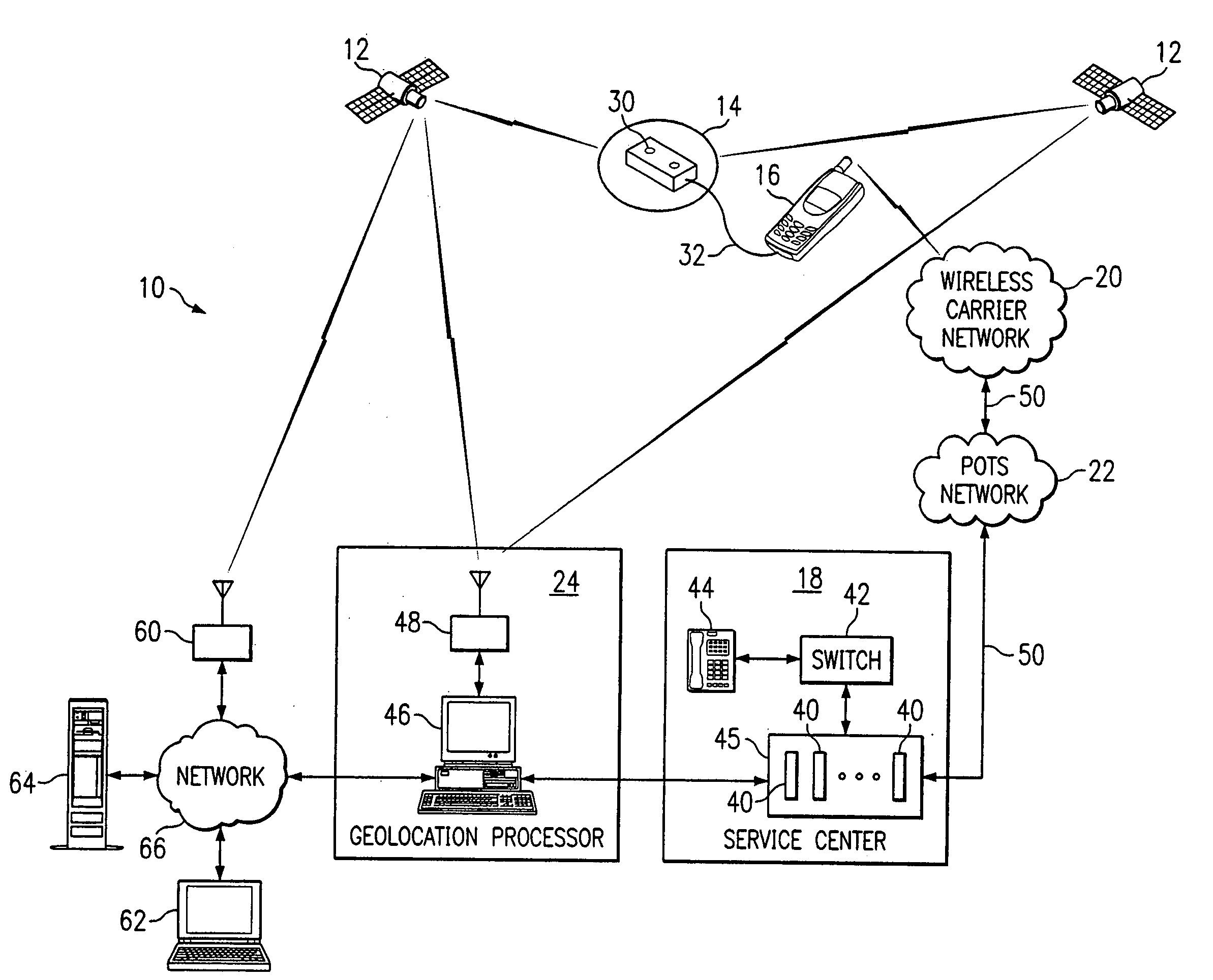
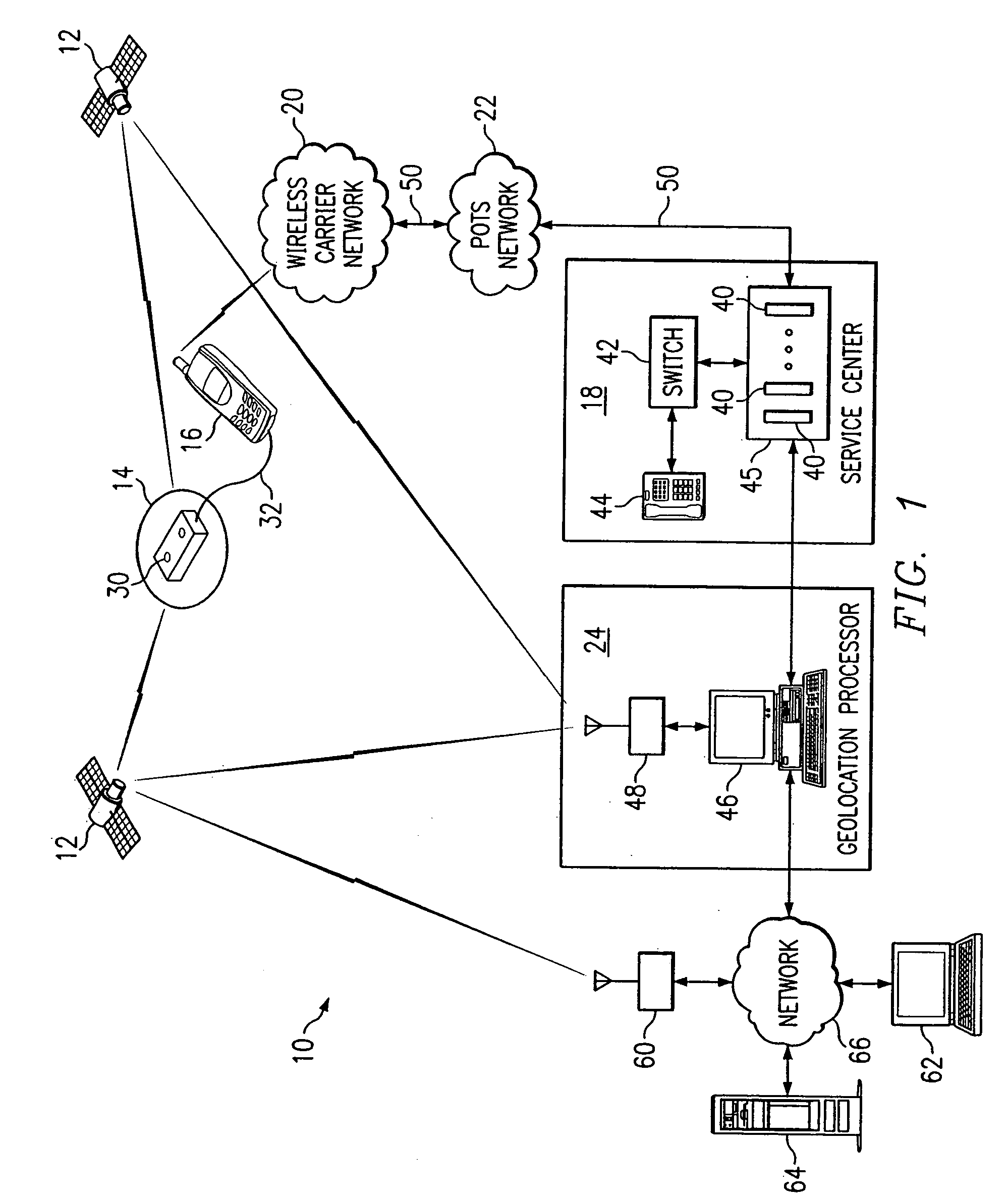
[0041]FIG. 1 is a block diagram illustrating a remote geolocation system 10 in accordance with one embodiment of the present invention. The system 10 may comprise a global positioning system (GPS), a global navigation satellite system (GLONASS), or other suitable navigation system.

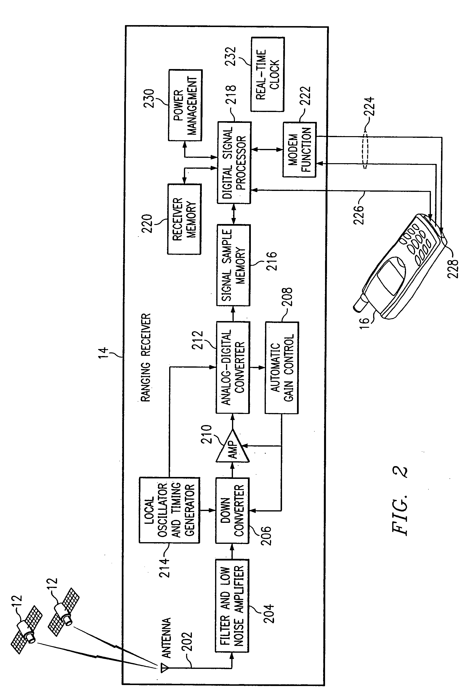
[0042] The system 10 comprises a plurality of positioning signal transmitters 12 and at least one ranging receiver 14. The positioning signal transmitters 12 are operable to transmit positioning signals, and each ranging receiver 14 is operable to receive the positioning signals and to perform geolocation processing functions in order to determine a pseudorange estimate for the ranging receiver 14 based on the received signals. As used herein, “each” means every one of at least a subset of the identified items. In the illustrated embodiment, the positioning signal transmitters 12 comprise satellites 12. Thus, as used herein, “satellites” means conventional satellites, pseudolites, or other suitable positi...


PUM


Abstract

A method and system for determining a geolocation of an object includes collecting a positioning signal including a predetermined message data segment. A time of arrival of the predetermined message data segment may be determined in the positioning signal. Information based on the time of arrival may be provided for determination of a geolocation of an object. The time of arrival of the predetermined message data segment may be determined based on a time search for the predetermined message data segment in the positioning signal.

Description

RELATED APPLICATIONS [0001] This application is divisional of U.S. patent application Ser. No. 10 / 445,232 entitled “METHOD AND SYSTEM FOR PROCESSING POSITIONING SIGNALS BASED ON PREDETERMINED MESSAGE DATA SEGMENT” (Attorney Docket 068796.0112), which is a continuation-in-part and claims the benefit of U.S. patent application Ser. No. 09 / 908,011, entitled “METHOD AND SYSTEM FOR PROCESSING POSITIONING SIGNALS IN A STAND-ALONE MODE” (Attorney's Docket 068796.0103), and also claims the benefit of U.S. Provisional Patent Application No. 60 / 383,353 filed May 24, 2002, entitled “PROCESSING WEAK SIGNALS FOR PSEUDORANGE WITHOUT MESSAGE ASSISTANCE AND WEAK SIGNAL GPS SATELLITE MESSAGE DECODING.”TECHNICAL FIELD OF THE INVENTION [0002] This invention relates generally to the field of geolocation and more particularly to a method and system for processing positioning signals based on a predetermined message data segment. BACKGROUND OF THE INVENTION [0003] In the application of global positioning...

Claims


Application Information

Patent Timeline
Patent Type & Authority Applications(United States)
IPC IPC(8): G01S19/25G01S1/00G01S5/00G01S5/14
CPCG01S5/0018G01S5/0063G01S19/05G01S19/09G01S19/17G01S19/235G01S2205/008G01S19/256G01S19/258G01S19/29G01S19/34G01S19/35G01S19/254
Inventor BROMLEY, PATRICK G.JANDRELL, LOUIS H. M.WISE, MICHAEL D.
Owner FAST LOCATION NET
Learn More