Label printer

a label printer and label technology, applied in the field of label printers, can solve the problems of paper jam, snagged moving blades on the cut surface, and medium occurrence, and achieve the effects of preventing naps, enhancing cutting performance, and facilitating cutting

Active Publication Date: 2005-07-28
BROTHER KOGYO KK
View PDF3 Cites 16 Cited by
  • Summary
  • Abstract
  • Description
  • Claims
  • Application Information

AI Technical Summary

Benefits of technology

[0013] Specifically, the label printer includes the cutter unit. The cutter unit includes the movable blade of a slide type where the movable blade is moved against the printing medium mounted in the housing in a direction of cutting the printing medium so that a part of the printing medium is cut into a print label. The cutting edge of the movable blade in the cutter unit is obliquely crossed with the direction of cutting the printing medium in such a manner that the upper portion of the cutting edge is inclined rearward, thereby ensuring the performance of cutting the printing medium (easiness of cutting) in its width direction.
[0014] Further, in the label printer, at the time of cutting the printing medium residing in a stable state by the cutter unit of the sliding type, the movable blade is reciprocated in a state where it obliquely crosses with the printing medium in a direction of feeding the printing medium. Since a shearing force is exerted onto the printing medium during the cutting operation, it is possible to prevent the occurrence of naps on the cut surface of the printing medium, and to further enhance the performance for cutting the printing medium (easiness of cutting) in its width direction.
[0015] Further, in the label printer, when the movable blade of the cutter unit is at the turning point of the movement, a state is established where the cutting edge of the movable blade goes beyond the side edge of the printing medium located at the side of the common reference, whereas the end portion of the cutting edge of the movable blade at the ridge side never goes beyond the side edge of the printing medium at the side of the common reference. Therefore, when the movable blade of the cutter unit advances in the cutting direction and then to reach the turning point from which the movable blade starts to advance in the direction reverse to the cutting direction, the cutting edge of the movable blade of the cutter unit completely passes through the printing medium and cuts a part of the printing medium from the printing medium. On the other hand, the end portion of the cutting edge of the movable blade of the cutter unit at the ridge side stays within the cut surface of the printing medium. Therefore, even when the movable blade of the cutter unit starts ...

Problems solved by technology

Thus, there is a fear that, when the movable blade comes to pass across the cut surface of the printing medium, the movable blade is snagged on the cut surface of the printing medium and paper jam and the like of the printing medium occurs.
However, at this time, since the printing ...

Method used


Image

  • Label printer
  • Label printer
  • Label printer

Examples


Embodiment Construction

[0073] A detailed description of a preferred embodiment of a label printer embodying the present invention will now be given referring to the accompanying drawings.

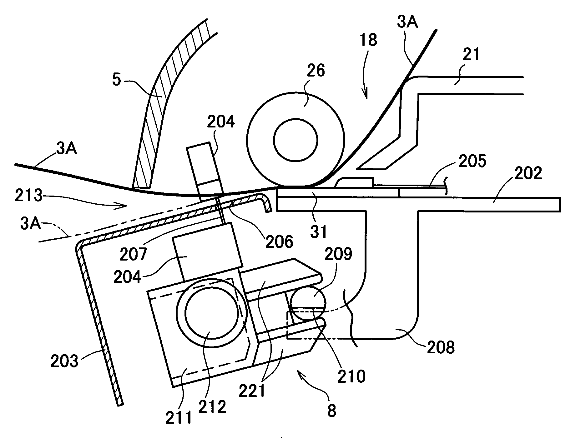
[0074] The label printer in the present embodiment is a model provided with a cutter unit of a sliding type. Firstly, the schematic structure of the whole label printer will be explained below with reference to FIGS. 1 to 7.

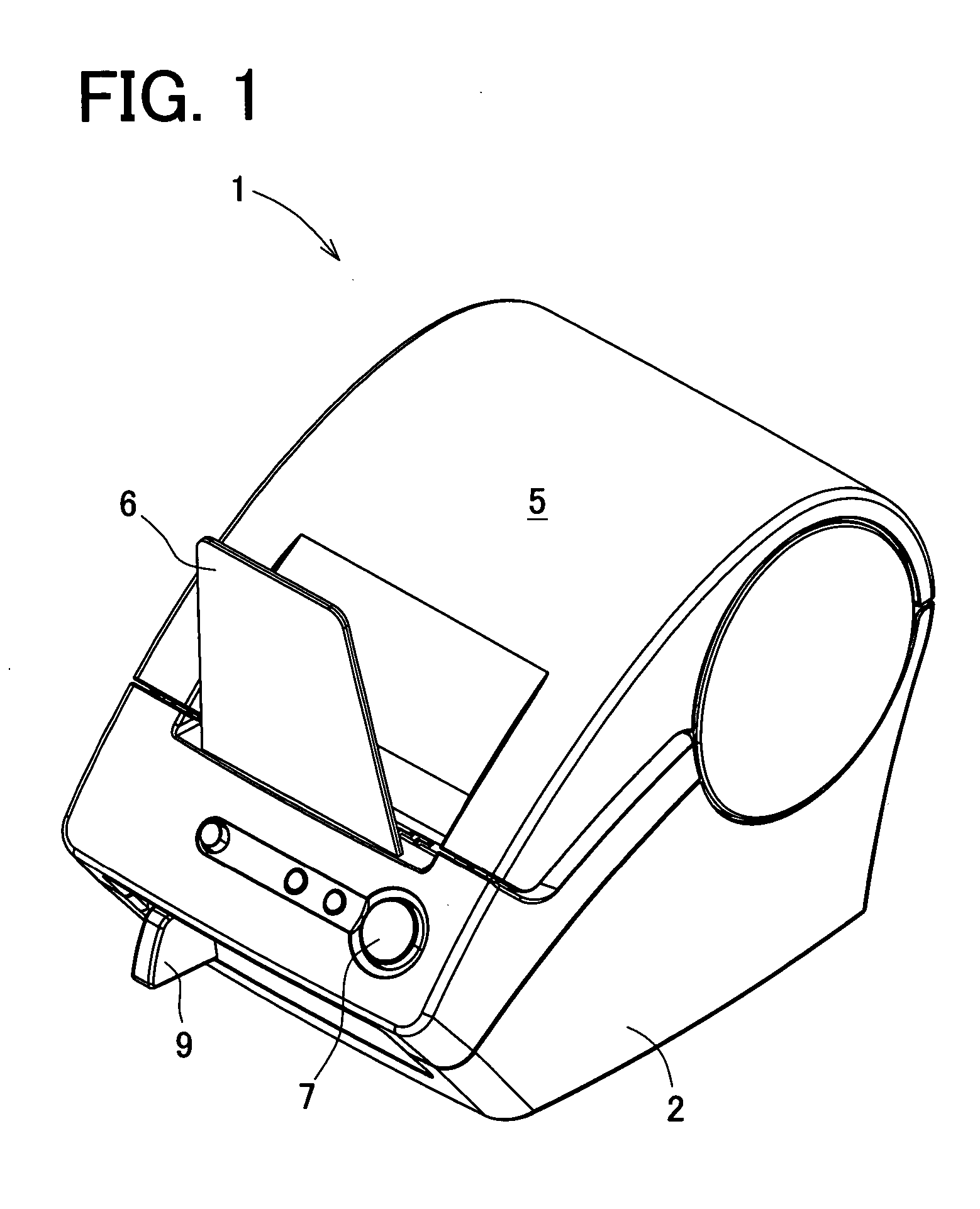
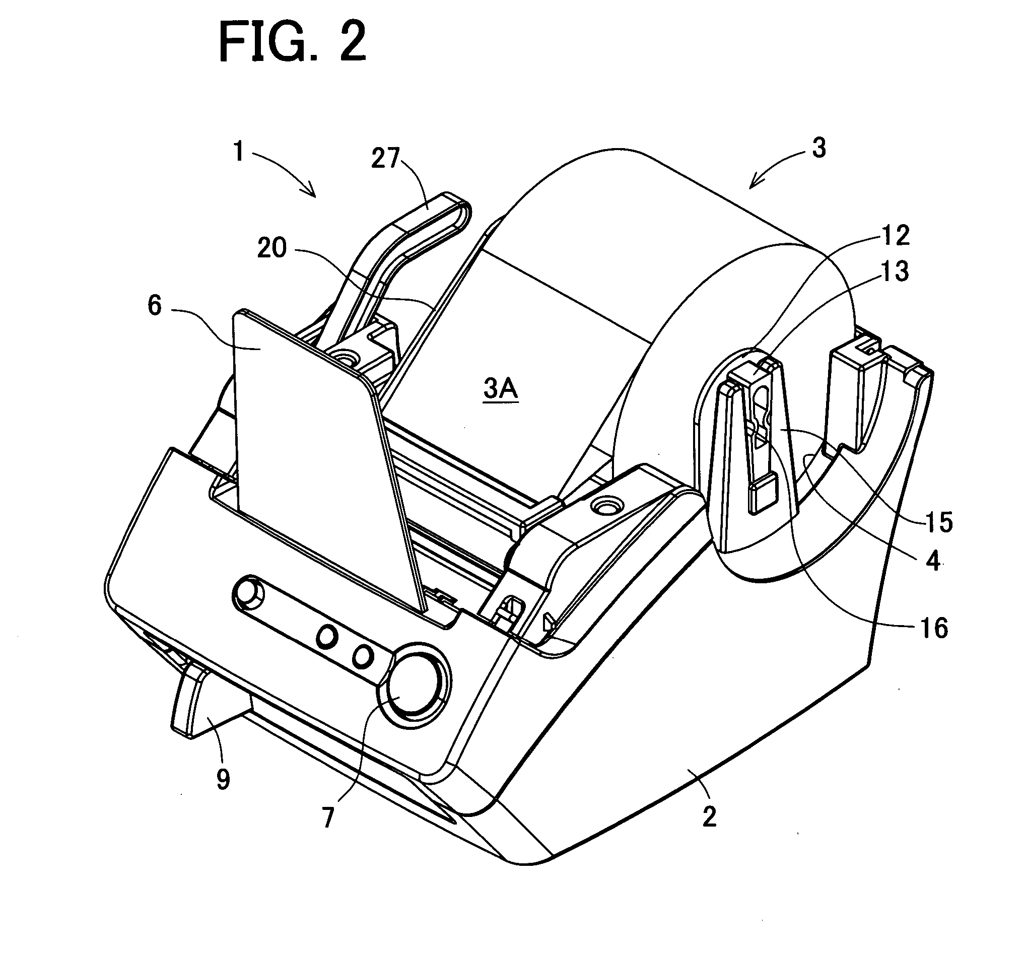
[0075] As shown in FIGS. 1 to 3, the label printer 1 includes a housing (a main body) 2, a top cover 5 made of transparent resin attached to the housing 2 at a rear upper edge, a tray 6 made of transparent resin set in a vertical position to face a substantially front center of the top cover 5, a power button 7 placed in front of the tray 6, a cutter lever 9 provided in a front face of the housing 2, and others. The top cover 5 is freely opened and closed, thereby covering an upper part of a roll sheet holder storage part (hereinafter, a “holder storage part”) 4 which is a space for receiving a roll ...


PUM


Abstract

A cutting edge of a movable blade mounted to a cutter holder is inclined at an oblique cross angle. The cutting edge of the movable blade obliquely intersects a roll sheet placed on a cutter plate in its cutting direction. This ensures that the cutting edge cuts the roll sheet sharply. On this regard, this oblique cross angle has an influence on the number of times that the cutting edge is capable of cutting. An appropriate range of the oblique cross angle is 24° and 34°. The oblique cross angle is an angle formed between an upper surface of the cutter plate and the cutting edge in the cutting direction of the movable blade.

Description

BACKGROUND OF THE INVENTION [0001] 1. Field of the Invention [0002] The present invention relates to a label printer for producing printed labels by sliding a movable blade so as to cut a long printing medium into pieces. [0003] 2. Description of Related Art [0004] In a conventional label printer, it is needed to cut a long printing medium at the time of producing printed labels. As one type to be employed in such a cutter unit, for example, there is a sliding type in which a movable blade is slid to cut a printing medium along its width direction into pieces (for example, see Japanese laid-open patent publication No. 2002-86823). [0005] On this regard, in this sliding type, at the time of cutting a printing medium into pieces, a movable blade is slid from its home position. In this sliding operation, the movable blade is moved to across the printing medium from its one side to the other side along the width direction. After this sliding operation is completed, in order to bring the...

Claims


Application Information

Patent Timeline
IPC IPC(8): B26D1/04B26D1/06B26D7/26B41J11/00B41J11/04B41J11/70B41J15/04B65H35/04
CPCB26D1/045B26D7/26B41J11/0025B41J15/042B41J11/703B41J11/706B41J11/009
Inventor SEO, KEIJISAGO, AKIRAKASUGAI, ATSUSHISUGIMOTO, KIYOSHI
Owner BROTHER KOGYO KK
Why Eureka
Try Eureka