Disk device integral type television receiver set and reproducing apparatus integral type television receiver set

Inactive Publication Date: 2005-07-28
FUNAI ELECTRIC CO LTD
View PDF7 Cites 2 Cited by
  • Summary
  • Abstract
  • Description
  • Claims
  • Application Information

AI Technical Summary

Benefits of technology

[0009] This invention has been accomplished in order to solve the above problems. An object of this invention is to provide a disk device integral type television receiver set and a reproducing apparatus integral type television receiver set which can prevent seizing on the screen of a CRT without increasing the storage capacity where still image data are continuously transmitted from the disk device to a television receiver and displayed on the CRT of the television receiver.
[0010] In accordance with this invention, there is provided a disk device integral type television receiver set including a disk device for reproducing a DVD or CD with an image recorded thereon, and a television receiver provided with a CRT on which the image is displayed on the basis of an output signal from a signal selecting unit for selecting either the data reproduced by the disk device or a broadcasting signal tuned by a tuner and with a speaker for producing a voice, characterized in that the disk device and the television receiver have control units for controlling their operation, respectively; the control unit of the disk device monitors the time during which the disk device continuously transmits still image data to the television receiver, and, if the time exceeds a prescribed time, sends a predetermined message to the television receiver, and the control unit of the television receiver having received the predetermined message causes the signal selecting unit to select the broadcasting signal to be displayed on the CRT in place of the still image data. In this configuration, where the still image is continuously displayed on the CRT for a time exceeding a predetermined time, the broadcasting image which is a moving image is displayed. This prevents the seizing of the screen on the CRT without increasing the storage capacity.
[0011] Further, in accordance with this invention, there is provided a reproducing device integral type television receiver set including a reproducing device for reproducing a recording medium with an image recorded thereon, and a television receiver provided with a video outputting unit on which the image is displayed on the basis of an output signal from a signal selecting unit for either the data reproduced by the reproducing device or a broadcasting signal tuned by a tuner and with an audio output unit for producing a voice, characterized in that a control unit is provided for the operation of the reproducing device and the television receiver; and the control unit monitors the time during which the reproducing device continuously transmits still image data to the television receiver, and, if the time exceeds a prescribed time, causes the signal selecting unit to select the broadcasting signal to be displayed on the video output unit in place of the still image data. In this configuration, where the still image is continuously displayed on the video output unit for a time exceeding a predetermined time, the broadcasting image which is a moving image is displayed. This prevents the seizing of the screen on the video output unit without increasing the memory capacity.
[0015] In accordance with this invention, even where still image data are continuously transmitted from a disk device to a television receiver, seizing of the screen of CRT of a television receiver can be prevented without increasing a storage capacity.

Problems solved by technology

However, these prior arts, in which the image data of the moving image for the screen saver, present a problem of an increase in the storage capacity of a memory.
The method disclosed in JP-A-8-287270 presents a problem that if the still image displayed on the entire screen is moved, a part of the displayed contents disappears.
This method may be not effective according to the display pattern of the still image.
The method disclosed in JP-A-2002-247528, in which the television image must be displayed at a small size at the corner of the screen, presents a problem of a reduction in a display area for the image to be reproduced by DVD.

Method used


Image

  • Disk device integral type television receiver set and reproducing apparatus integral type television receiver set
  • Disk device integral type television receiver set and reproducing apparatus integral type television receiver set
  • Disk device integral type television receiver set and reproducing apparatus integral type television receiver set

Examples


Embodiment Construction

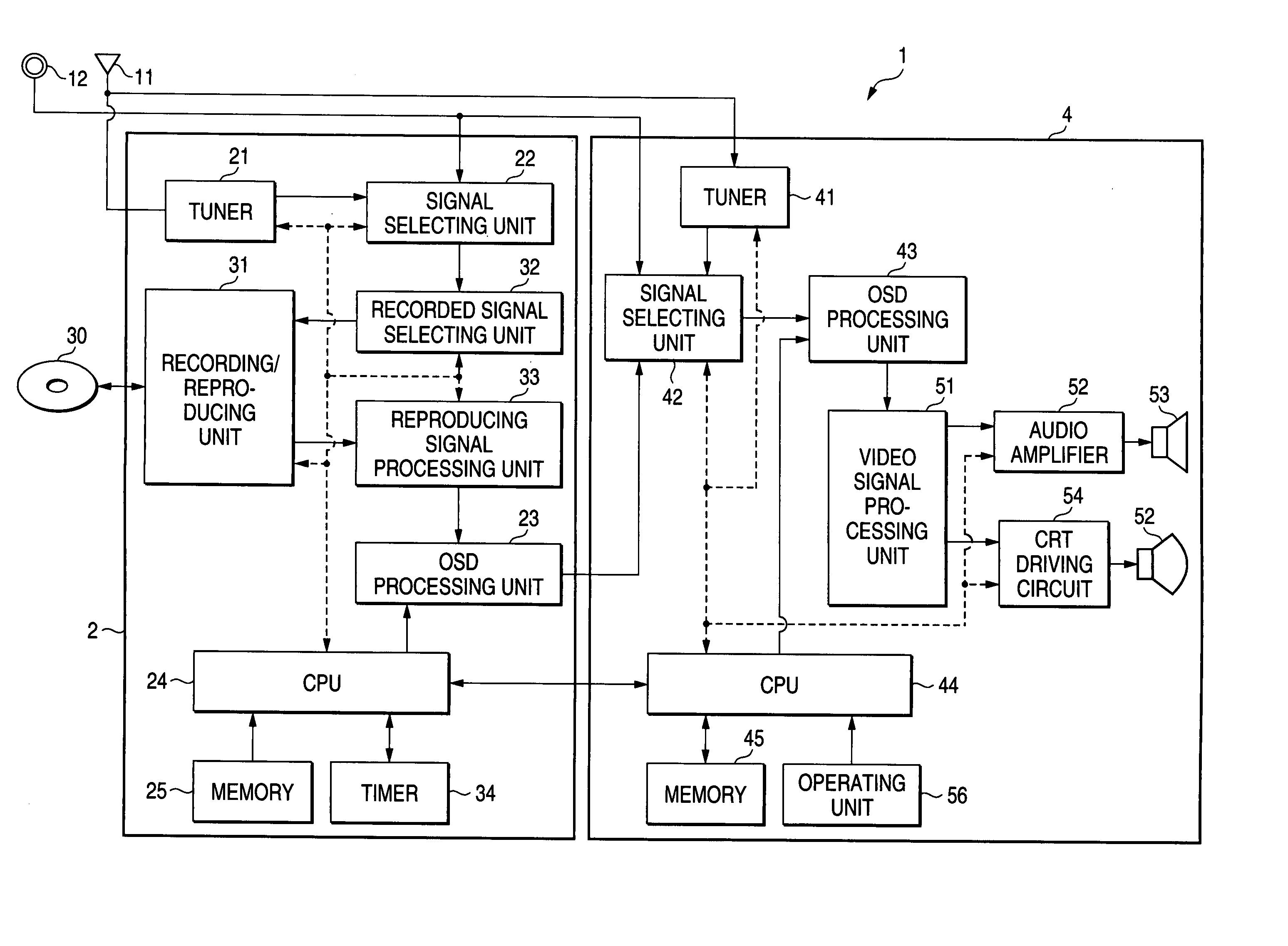
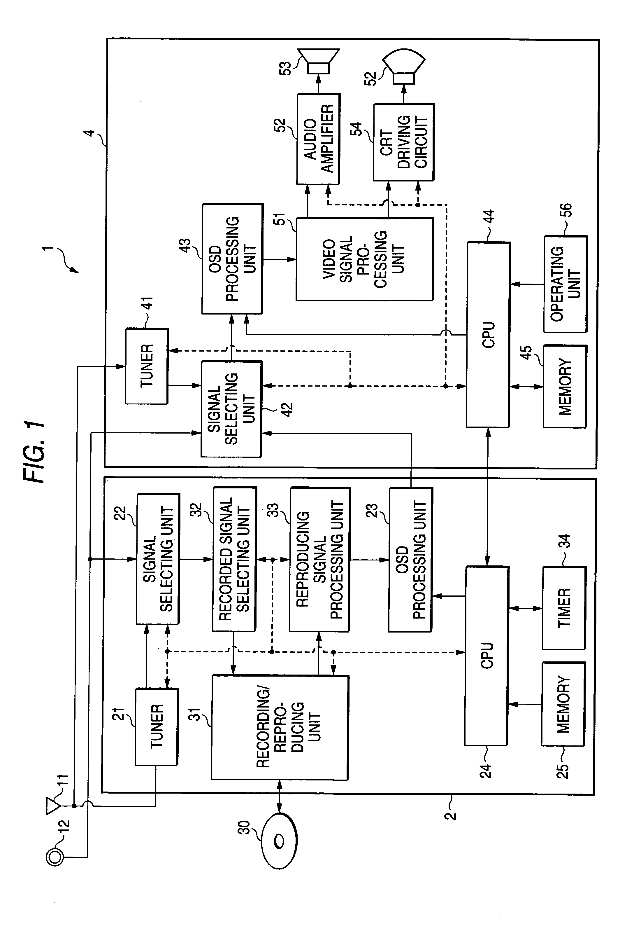
[0021]FIG. 1 is a block diagram of a disk device integral type television receiver set 1 according to this invention. The disk device integral type television receiver 1 includes a disk device 2 and a television receiver 4. First, the configuration of the disk device 2 will be explained. The disk device 2 is designed so that it can reproduce a disk 30 which may be various media such as DVD and CD and carry out recording for a writable disk 30.

[0022] A broadcasting signal received at an antenna 11 is tuned by a tuner 21. The tuned signal is transmitted to a signal selecting unit 22. In the signal selecting unit 22, the broadcasting signal or a signal from an external input terminal 12 is selected on the basis of the signal supplied from a CPU 24. The selected signal is transmitted to a recorded signal processing unit 32. The signal from the external input terminal 12 may be an output signal from other audio / video appliances, e.g. video tape recorder. In the recorded signal processin...


PUM


Abstract

In a disk device integral type television receiver set, when the transmission of data of a still image from a disk device side to a television receiver side is started, a timer is started. As a result that the display of the still image has been continued, when the time set in the timer has elapsed (times up), the CPU of the disk device side informs the CPU of the television receiver of this fact. The CPU of the television receiver side having been informed sends, to a signal selecting unit, a signal of selecting a broadcasting signal from a tuner. Thus, a broadcasting image which is a moving image is displayed on a CRT.

Description

BACKGROUND OF THE INVENTION [0001] 1. Field of the Invention [0002] This invention relates to a disk device integral type television receiver set and a reproducing apparatus integral type television receiver set. [0003] 2. Description of the Related Art [0004] In a DVD player or the like, when a still image data such as a disk menu screen of DVD is displayed for a long time on a CRT (cathode ray tube) of a television receiver, seizing of the screen occurs. [0005] In order to solve this problem, it has been widely known that where [0006] the display of the still image is continued for a prescribed time or longer, a screen saver is actuated to display a moving image on the CRT (for example, JP-A-2002-247528). [0007] JP-A-11-4390 discloses that in order to prevent the screen seizing due to the “on-screen display” during CD reproduction, the position of the “on-screen display” is moved on the on the screen at regular time intervals. JP-A-8-287270 discloses that in a document creating ap...

Claims


Application Information

Patent Timeline
IPC IPC(8): H04N5/45H04N5/76H04N5/775H04N5/781H04N5/85
CPCH04N5/44H04N5/775H04N5/85H04N21/42646H04N21/8153H04N21/4383H04N21/44222H04N21/4532H04N21/4622H04N21/4325
Inventor TAKAHASHI, RYUJI
Owner FUNAI ELECTRIC CO LTD
Why Eureka
Try Eureka