Projector

a projector and projection device technology, applied in non-linear optics, instruments, optical elements, etc., can solve the problems of inability to obtain proper projection performance, uneven thickness of the adhesive layer formed between, and considerable time consumed in the process, so as to reduce the time for assembling and manufacturing. time, easy positioning, the effect of reducing the manufacturing cos

Inactive Publication Date: 2005-07-28
FUJI PHOTO OPTICAL CO LTD
View PDF20 Cites 24 Cited by
  • Summary
  • Abstract
  • Description
  • Claims
  • Application Information

AI Technical Summary

Benefits of technology

[0012] According to the present invention, the space for the adhesive layer is formed with the prism and the base plate being closely contact to each other because of the projection formed on the base plate for supporting the prism. Therefore, the prism is never inclined by uneven thickness of the adhesive layer when being fixed to the base plate, because the prism can be positioned to the base plate before fixing. And time for assembling can be reduced because the second bracket for holding the image display device is easily positioned owing to the projection, and a process for fixing the bracket to the base plate and a process for fixing the prism to the base plate can be performed at the same time. In addition, manufacturing cost can be reduced because the prism having smaller size can be used in comparison with a case that frames and so on are fixed to a side surface of a prism optically polished.
[0013] A time for fixation (curing) can be substantially shortened by using the UV curing resin as the adhesive agent, in comparison with the conventional methods of using epoxy resin to fix a frame to a side surface of a prism, and using silicon resin to fix a base plate to a bottom surface of a prism.
[0014] The manufacturing cost is further reduced by that the first bracket and the second bracket have the same shape. Although the first bracket which is not fixed by the base plate should be adhered to the prism, the first bracket can be fixed with closely contacting with the prism by the adhesive agent being applied to an opening formed on the first bracket.
[0015] Because the holes where the holding arms are inserted are provided on the image display device to fix the image display device to the first and the second bracket, the liquid-crystal panel can be moved in a clearance between the hole and the holding arm. Therefore, fine adjustment of the position of the image display device can be easily performed.

Problems solved by technology

However, in the above described prior arts, because the bottom surface of the cross-dichroic prism is adhered directly to a base plate, an adhesive layer formed in between can be uneven in thickness.
In this state, proper projection performance cannot be obtained even if a position of the liquid-crystal display for attaching to the prism is changed.
This process consumes considerable time.

Method used


Image

  • Projector
  • Projector
  • Projector

Examples


second embodiment

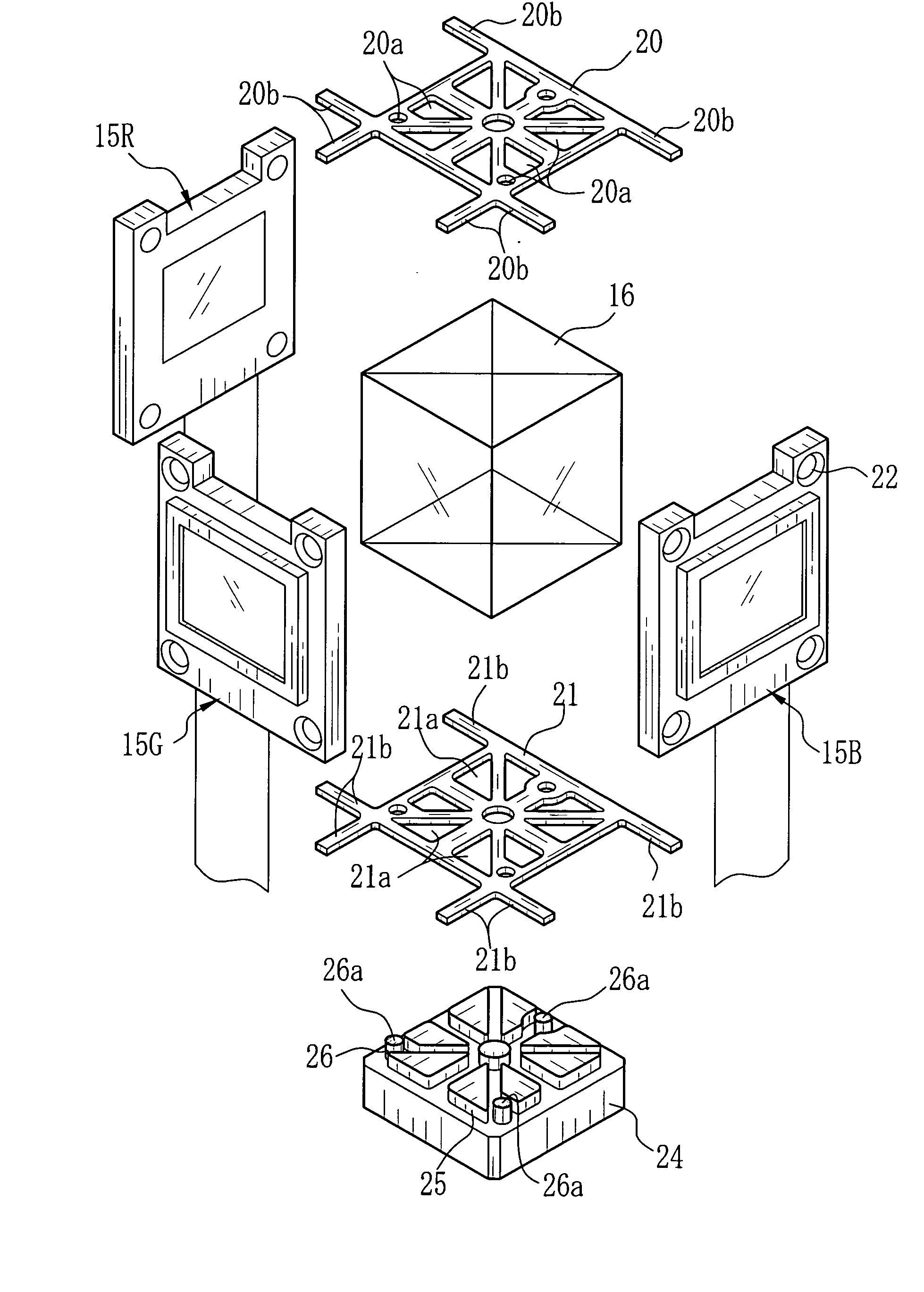
[0041] Now the present invention is explained. In FIG. 7, on a base plate 30, four first projections 30a which have cylindrical shape and three second projections 30b which are taller than the first projections 30a are provided. In a lower bracket 31, first openings 31a for being fitted onto the first projections 30a and second openings 31b for being fitted onto the second projections 30b are provided. The second projections 30b are projected from the lower bracket 31 when the lower bracket 31 is attached to the base plate 30, for supporting the bottom surface of the cross-dichroic prism 16.

[0042] On the top surface of the cross-dichroic prism 16, three upper brackets 32 are provided. The upper bracket 32 provides adhesion surfaces 32a for being adhered with an attachment frame 34 to which a liquid-crystal panel 33 is attached, and an opening 32b where the adhesive agent is applied to fix the upper bracket 31 on the cross-dichroic prism 16. The attachment frame 34 provides upper leg...

first embodiment

[0045] After the liquid-crystal panel 33 is attached on the attachment frame 34, the adhesive agent is applied to the upper leg portions 34a and the lower leg portions 34b, and these portions are closely contacted to the adhesion surfaces 31c, 32a of the upper and lower brackets 31, 32. As with the above described first embodiment, the adhesive agent is cured after adjusting the positions of the three liquid-crystal panels such that the respective color images from the respective liquid-crystal panels are superimposed with accuracy. Accordingly, the all liquid-crystal panels are integrally held with the cross-dichroic prism 16 through the upper and lower brackets 31 and 32.

[0046] Note that in the above embodiments, the transmissive type of the liquid-crystal projector in which the liquid-crystal panel as the image display device, and the cross-dichroic prism for composing the three color light beams are provided, is used. However, the present invention is not limited to this type of...


PUM

PropertyMeasurementUnit
wavelengthaaaaaaaaaa
heightaaaaaaaaaa
thicknessaaaaaaaaaa

Abstract

In a base plate, projections for being inserted into openings in a lower bracket, and for supporting a bottom surface of a cross-dichroic prism, are provided. The lower bracket and the cross-dichroic prism are fixed to the base plate by adhesive agent filled into a clearance between the lower bracket and the bottom surface of the cross-dichroic prism supported on the projections. Holes are provided on a liquid-crystal panel, and holding arms provided on an upper bracket and the lower bracket are inserted into the holes. Then the adhesive agent is applied into the holes to fix the liquid-crystal display to the upper and lower brackets.

Description

BACKGROUND OF THE INVENTION [0001] 1. Field of the Invention [0002] The present invention relates to a projector assembled such that an image display device such as a liquid-crystal panel is integrally held around a prism for composing or decomposing light beams. [0003] 2. Description Related to the Prior Art [0004] It is well known three-panel type liquid-crystal projectors which decompose the white light into red light, green light, and blue light, modulate the three color light to an image light by using image display devices corresponding to respective color light, and then compose the three color image lights and project the composed image light. For example, in a three-panel type liquid-crystal projector having liquid-crystal panels of transmissive type, a cross-dichroic prism having two dichroic surfaces which are orthogonal to each other composes three color light beams having passed through each liquid-crystal panel. The cross-dichroic prism has a rectangular solid shape, a...

Claims


Application Information

Patent Timeline
Patent Type & Authority Applications(United States)
IPC IPC(8): G02F1/13G02F1/1333G02B7/18G02F1/1335G03B21/00G03B21/14G03B21/28
CPCG02B7/1805H04N9/317G03B21/14G03B21/145G03B21/2066G03B33/12
Inventor SHIROTA, KEI
Owner FUJI PHOTO OPTICAL CO LTD
Why Eureka
Try Eureka