
Lithographic apparatus and device manufacturing method

a technology of lithographic apparatus and manufacturing method, which is applied in the direction of photomechanical apparatus, instruments, optics, etc., can solve the problems of no useful radiation or operation time expended for exposing the test surface, no direct access to the beam path, and may be required for interruption of normal operation

Inactive Publication Date: 2005-07-28
ASML NETHERLANDS BV
View PDF6 Cites 13 Cited by
  • Summary
  • Abstract
  • Description
  • Claims
  • Application Information

AI Technical Summary

Benefits of technology

[0009] Among others it is an aspect of the present invention to provide a lithographic apparatus and a device manufacturing method that allow for sensitive detection whether undesirable gases are present in undesirable amounts in the atmosphere near the optical elements.
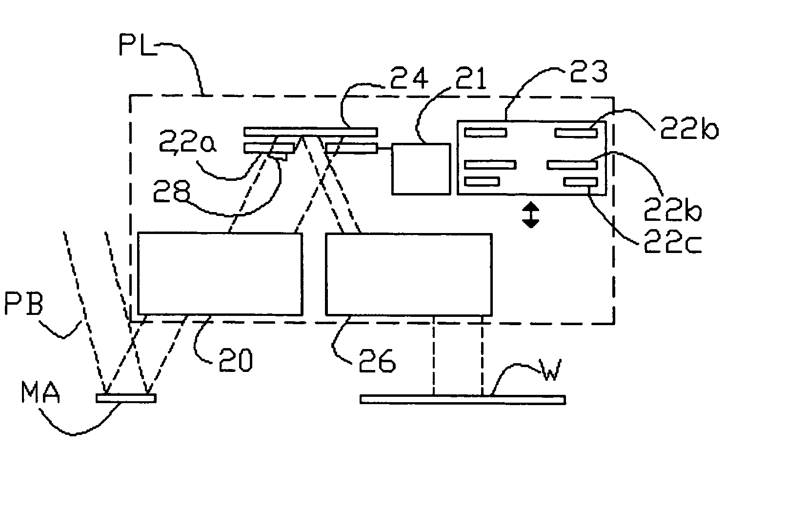
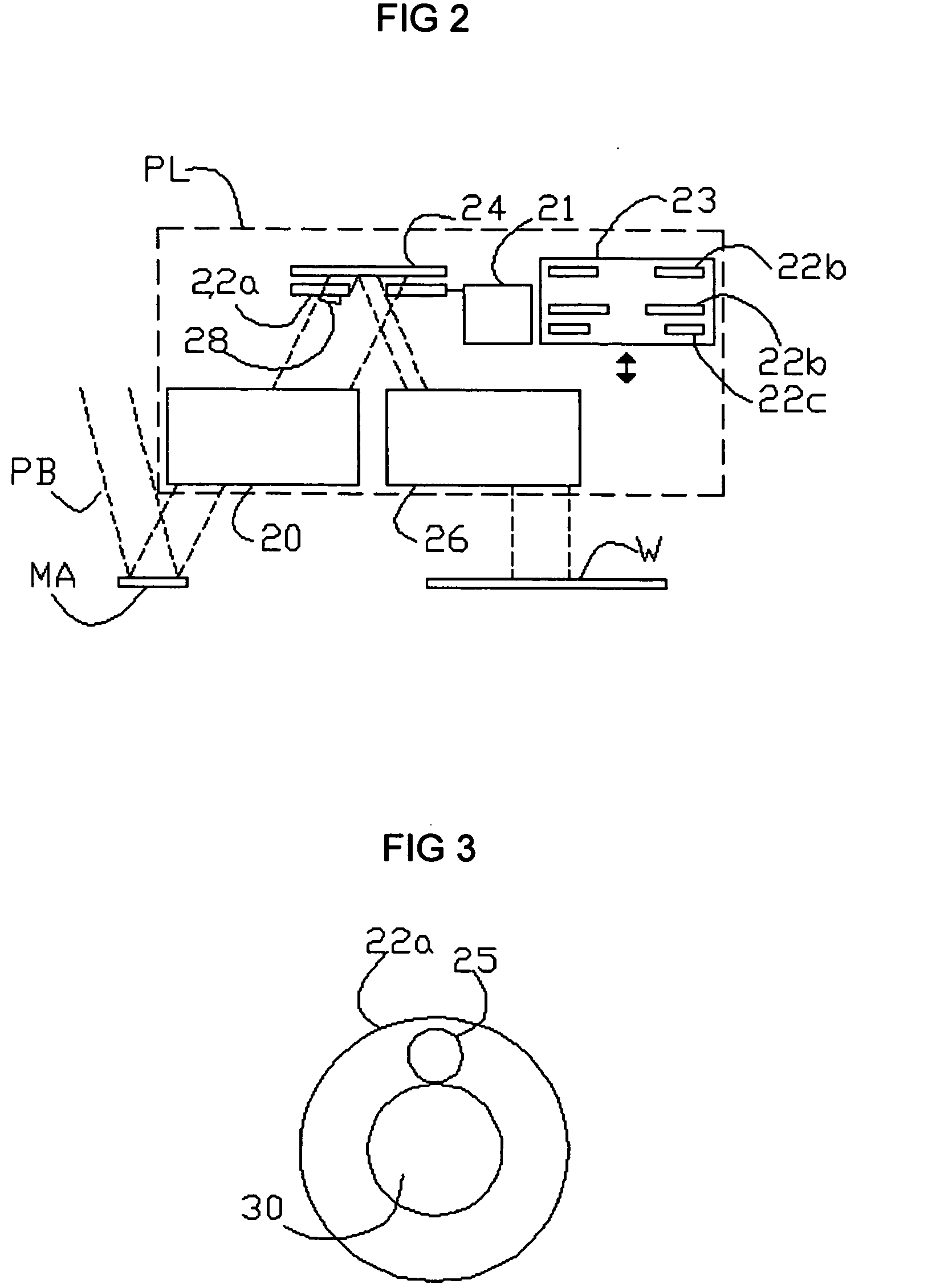
[0012] Preferably, the test surface is made of the same material as that of an optical element such as a reflector lens that is used to pass the beam to the substrate. In the case of a test surface of reflective material the test surface may be provided at an angle with the main surface of the aperture screen that extends in the plane defined by the circumference of the opening in the screen (the angle being at least one degree for example), so that the test surface does not reflect radiation from the beam into the beam path.
[0015] By providing the test surface on the aperture screen the test surface is on one hand highly accessible for examination, because it can be taken from the storage unit for examination without directly intervening in the beam path, and on the other hand the test surface is exposed to a maximum of radiation from the beam without wasting radiation that could be used for exposing the substrate.
[0016] Preferably, different aperture screens are each provided with their own test surface. In this way it is possible to get a maximum amount of information. It may be detected for example whether there is a correlation between formation of reaction products and specific processing steps for which specific aperture screens are used.

Problems solved by technology

Thus, no useful radiation or operation time has to be expended for exposing the test surface.
This means that no direct access to the beam path, or interruption of normal operation may be required to extract the aperture screen for inspection of the test surface.

Method used


Image

  • Lithographic apparatus and device manufacturing method
  • Lithographic apparatus and device manufacturing method
  • Lithographic apparatus and device manufacturing method

Examples


Embodiment Construction

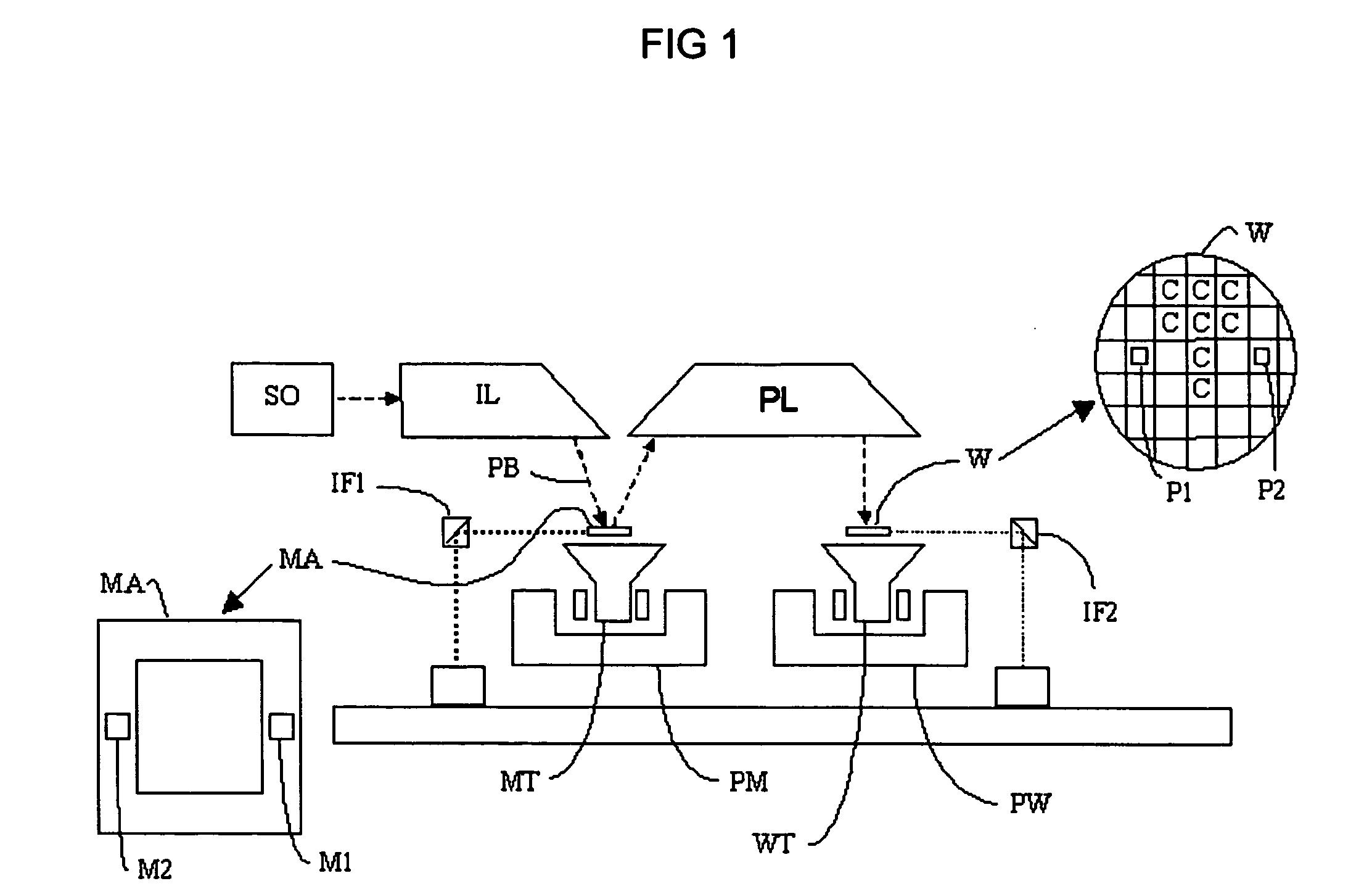
[0030]FIG. 1 schematically depicts a lithographic apparatus according to an embodiment of the invention. The apparatus comprises: an illumination system (illuminator) IL for providing a projection beam PB of radiation (e.g. UV or EUV radiation); a first support structure (e.g. a mask table) MT for supporting a patterning device (e.g. a mask) MA and connected to a first positioning structure PM for accurately positioning the patterning device with respect to item PL; a substrate table (e.g. a wafer table) WT for holding a substrate (e.g. a resist-coated wafer) W and connected to a second positioning structure PW for accurately positioning the substrate with respect to item PL; and a projection system (e.g. a reflective projection lens) PL for imaging a pattern imparted to the projection beam PB by patterning device MA onto a target portion C (e.g. comprising one or more dies) of the substrate W.

[0031] As here depicted, the apparatus is of a reflective type (e.g. employing a reflecti...


PUM

PropertyMeasurementUnit
timeaaaaaaaaaa
angleaaaaaaaaaa
wavelengthaaaaaaaaaa

Abstract

In a lithographic apparatus, a beam of radiation passes along a beam path to a substrate, for applying patterned illumination to the substrate. An exchangeable aperture screen is inserted in the beam path to partially block out the beam from a remainder of the path onto the substrate. A test surface is provided on the aperture screen, so that the test surface receives a part of the beam that is not passed along the remainder of the beam path. The test surface is made of a material that is sensitive, under influence of radiation from the beam, to chemical alterations that also affect the optical element under influence of radiation from the beam. The test surface is later analyzed for chemical alterations after exposure to the beam.

Description

BACKGROUND OF THE INVENTION [0001] 1. Field of the Invention [0002] The present invention relates to a lithographic apparatus and a device manufacturing method. [0003] 2. Brief Description of Related Art [0004] A lithographic apparatus is a machine that applies a desired pattern onto a target portion of a substrate. Lithographic apparatus can be used, for example, in the manufacture of integrated circuits (ICs). In that circumstance, a patterning device, such as a mask, may be used to generate a circuit pattern corresponding to an individual layer of the IC, and this pattern can be imaged onto a target portion (e.g. comprising part of, one or several dies) on a substrate (e.g. a silicon wafer) that has a layer of radiation-sensitive material (resist). In general, a single substrate will contain a network of adjacent target portions that are successively exposed. Known lithographic apparatus include so-called steppers, in which each target portion is irradiated by exposing an entire ...

Claims


Application Information

Patent Timeline
Patent Type & Authority Applications(United States)
IPC IPC(8): G03F7/20
CPCG03F7/70483G03F7/70983G03F7/70916G03F7/7085
Inventor MOORS, JOHANNES HUBERTUS JOSEPHINAMICKAN, UWE
Owner ASML NETHERLANDS BV
Learn More