Cooling body

Inactive Publication Date: 2005-07-28
ROBERT BOSCH GMBH
View PDF10 Cites 1 Cited by
  • Summary
  • Abstract
  • Description
  • Claims
  • Application Information

AI Technical Summary

Problems solved by technology

Due to these previous means of fastening the spring element to the main body, the known heat sinks are relatively costly to manufacture.

Method used


Image

  • Cooling body
  • Cooling body
  • Cooling body

Examples


Embodiment Construction

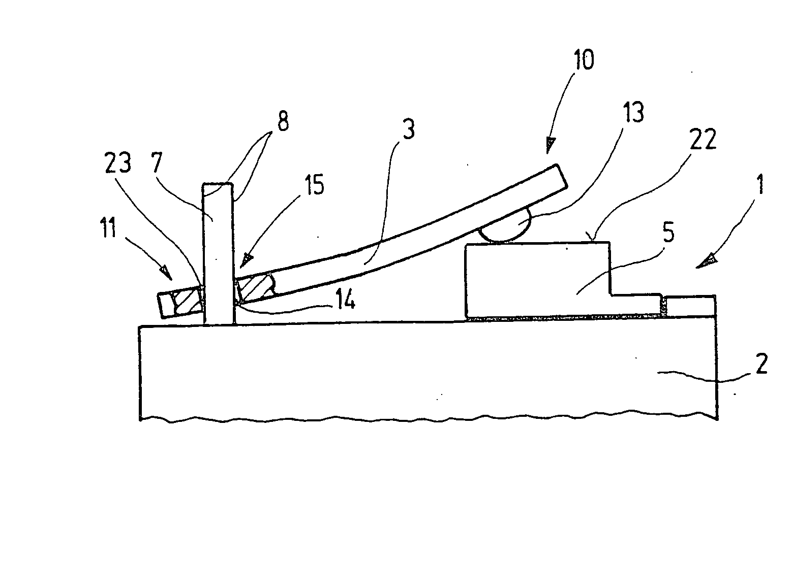
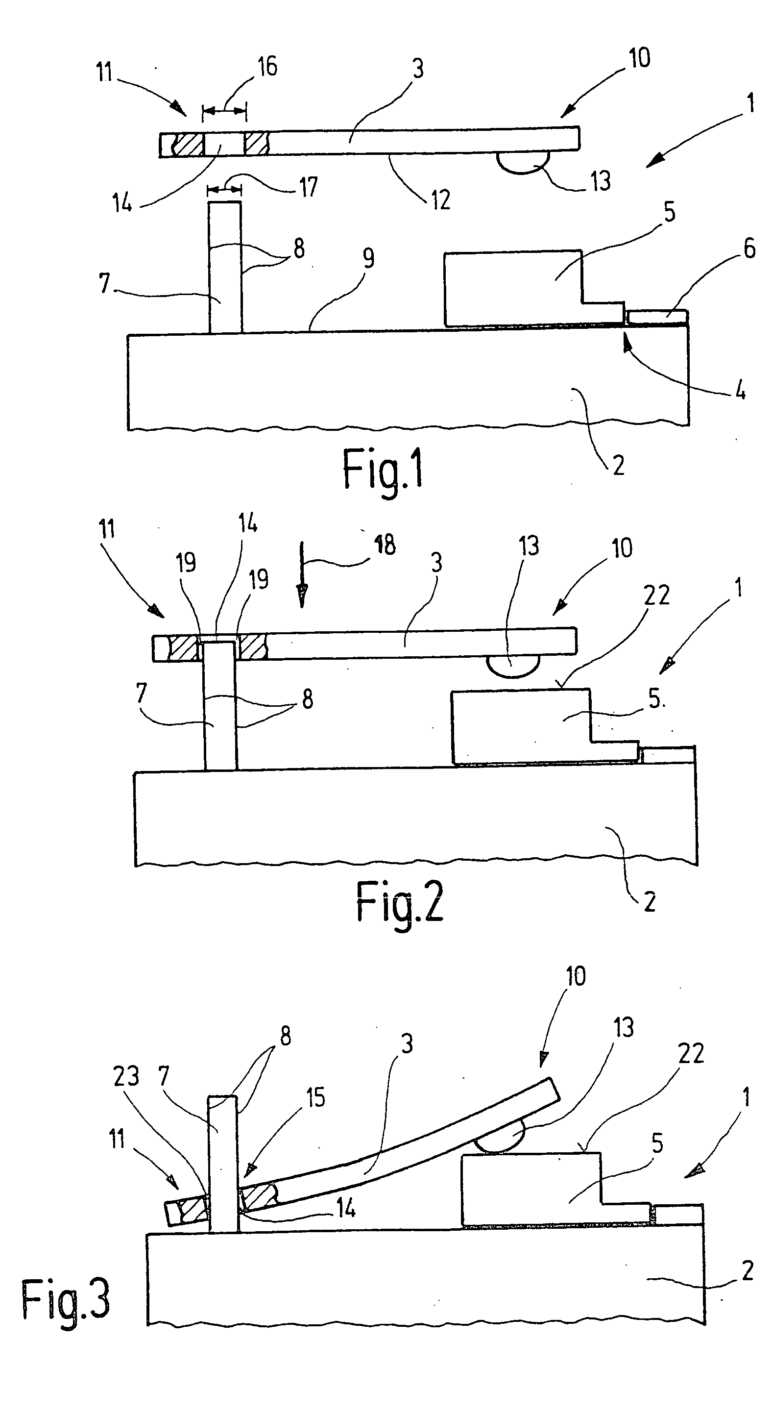
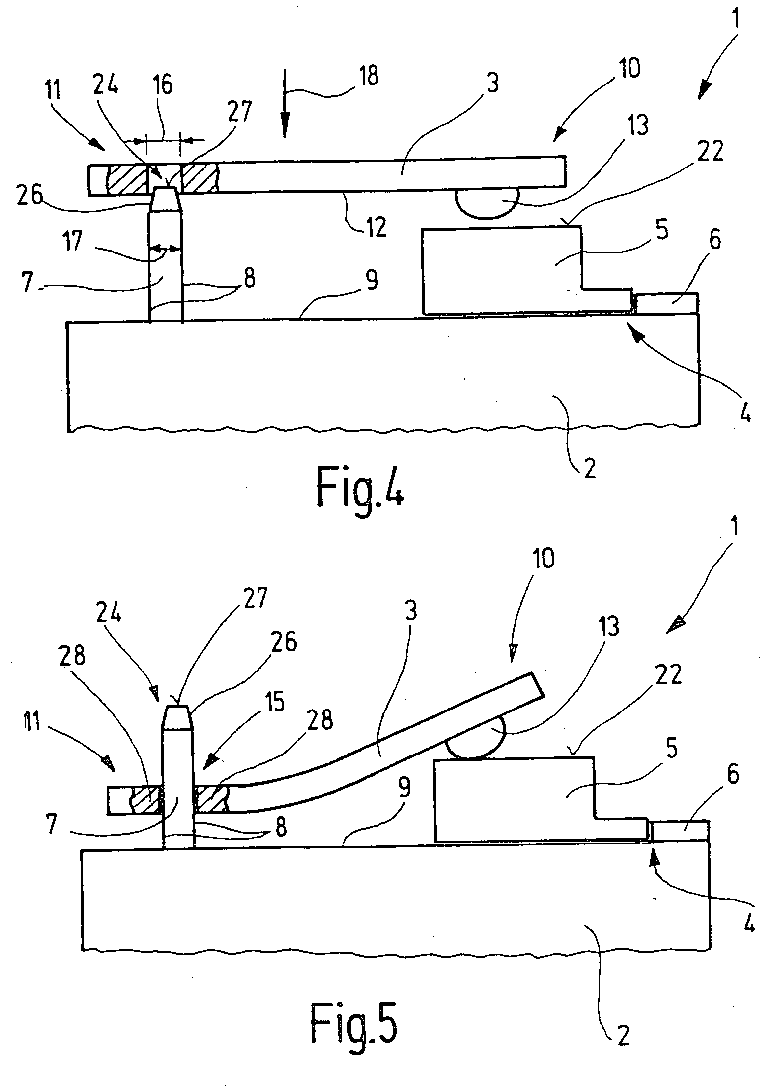
[0021]FIG. 1 shows, in a schematic representation, a heat sink 1 with a main body 2 and a spring element 3, before installation of spring element 3. Main body 2 has a receptacle 4 for accommodating an electronic structural element 5. Receptacle 4 of main body 2 contains a stop 6 for positioning structural element 5. Main body 2 further includes a projection 7 which extends, with its longitudinal side 8, at an angle of 90° and / or at an angle of essentially 90° to a top side 9 of main body 2. Spring element 3, which is configured as a leaf spring in the form of a flat spring, has a first end region 10 and a second end region 11, as viewed longitudinally. On its side 12 facing main body 2, first end region 10 contains a contact point 13 for electronic structural element 5.

[0022] In this exemplary embodiment, contact point 13 is configured as a projecting element opposite side 12 of spring element 3. The projecting element can be formed via material deformation of first end region 10 u...


PUM


Abstract

The present invention relates to a heat sink (1) with a main body (2) for accommodating at least one electronic structural element (5), and with a spring element (3) for pressing the structural element (5) against the main body (2), whereby the spring element (3) is held on the main body (2) by a connecting means. It is provided that the connecting means are configured as a push-on connection (15) and have a projection (7) on the main body (2) and a mounting opening (14) in the spring element (3) for the projection (7), whereby the opening edge (23) of the mounting opening (14) bears, at least in sections, against the lateral surface of the projection (7) under preload resulting from the intrinsic elasticity of the spring element (3) and / or the projection (7).

Description

[0001] The present invention relates to a heat sink with a main body for accommodating at least one electronic structural element, and with a spring element for pressing the structural element against the main body, whereby the spring element is held on the main body by a connecting means, according to the definition of the species of claim 1. BACKGROUND INFORMATION [0002] Heat sinks of the type discussed here are known. They are used to absorb the heat dissipated from semiconductors in electronic circuits. To this end, the semiconductor is pressed onto a main body of the heat sink by a spring element. The spring element itself is held on the main body by latching into undercuts in the main body or being staked in a recess of the main body. Due to these previous means of fastening the spring element to the main body, the known heat sinks are relatively costly to manufacture. ADVANTAGES OF THE INVENTION [0003] In contrast to the related art, the heat sink according to the invention h...

Claims


Application Information

Patent Timeline
IPC IPC(8): H01L23/40
CPCH01L23/4093H01L2924/0002H01L2924/00
Inventor KIMMICH, PETER
Owner ROBERT BOSCH GMBH
Why Eureka
Try Eureka