Optical recording medium having dual information surfaces

a technology of optical recording medium and information surface, which is applied in the field of optical recording medium, can solve the problems of inconvenient handling of recording medium, small storage capacity of such a cd, and above conventional techniques, and achieve the effect of convenient printing

Inactive Publication Date: 2005-07-28
PANASONIC CORP
View PDF51 Cites 7 Cited by
  • Summary
  • Abstract
  • Description
  • Claims
  • Application Information

AI Technical Summary

Benefits of technology

[0020] Thus, the invention described herein makes possible the advantages of (1) providing an optical recording medium having dual information surfaces where a label can be easily printed on a surface of the recording medium, information can be automatically reproduced by use of one optical head, and the compatibility with an optical recording medium having one information surface can be secured, and (2) providing an optical recording medium which includes a substrate with a thickness different from the conventional standard but is compatible with conventional apparatuses so that information stored in the optical recording medium can be reproduced.

Problems solved by technology

The storage capacity of such a CD is small because the CD has only one information surface.
However, the above conventional techniques have the following problems.
This is inconvenient for handling the recording medium.
An apparatus having two optical heads is large in size and its cost is high.
Another problem is that when a new optical recording medium thinner than the conventional optical recording media is commercialized to increase the density of the recording medium, such a new optical recording medium is not compatible with the conventional recording / reproduction apparatus.

Method used


Image

  • Optical recording medium having dual information surfaces
  • Optical recording medium having dual information surfaces
  • Optical recording medium having dual information surfaces

Examples


example 1

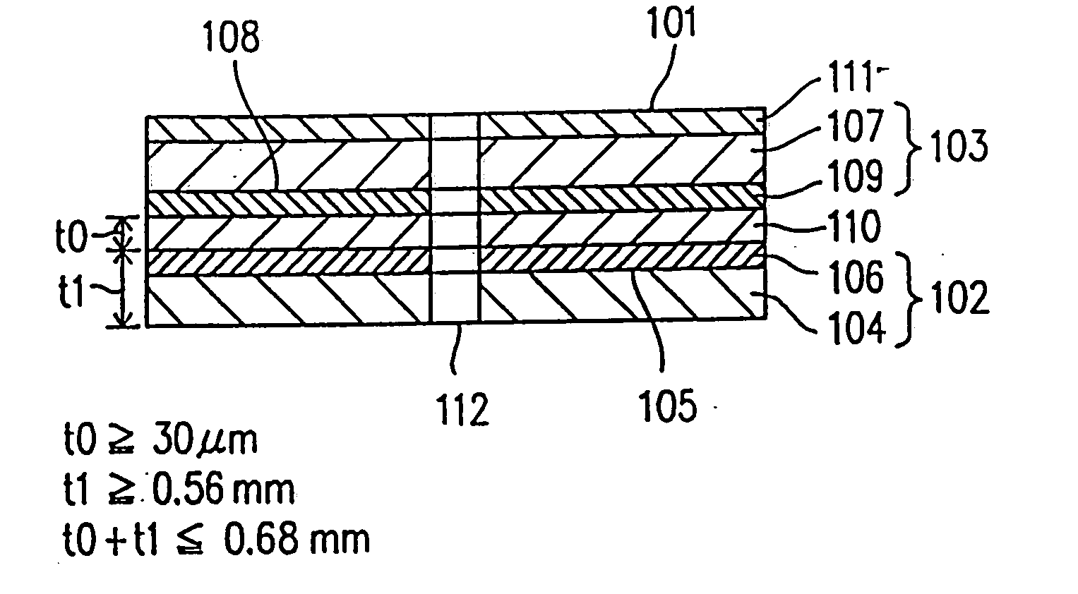
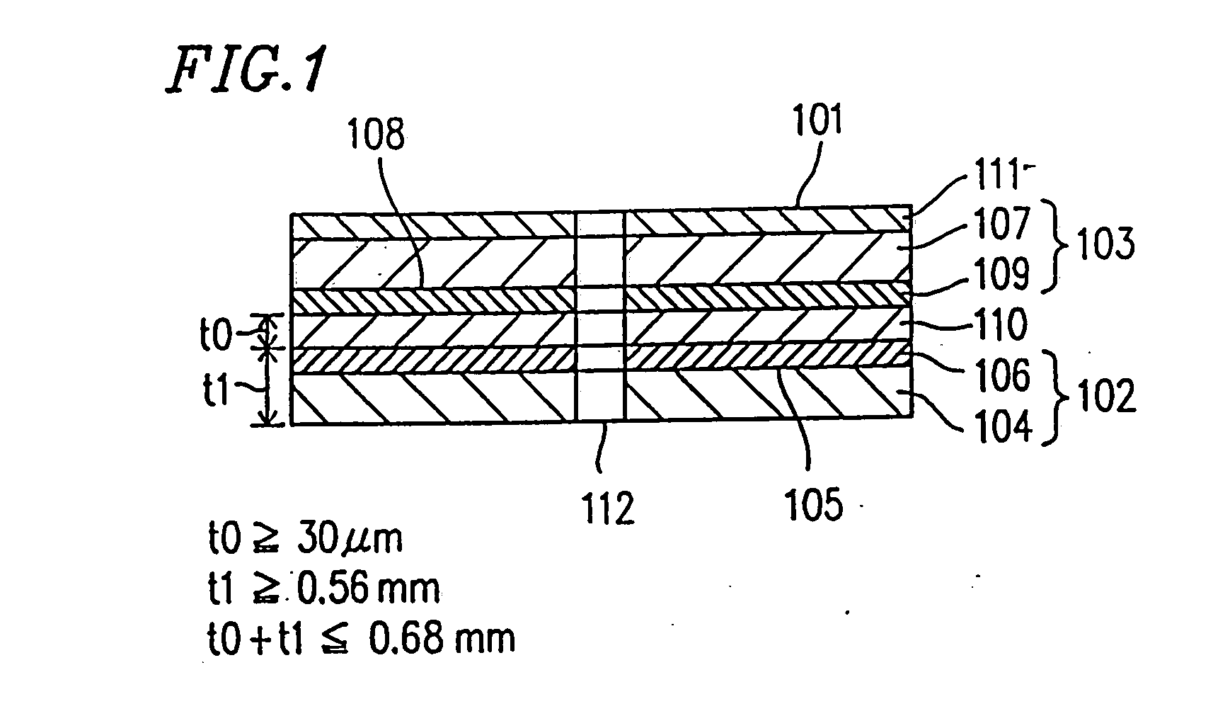
[0030]FIG. 1 is a schematic sectional view showing an optical recording medium 101 of Example 1 according to the present invention. The optical recording medium 101 is a one-side read type recording medium composed of a first optical disk 102 and a second optical disk 103 adhered to each other. Such an optical recording medium can provide excellent performance as & digital video disk (DVD).

[0031] The first optical disk 102 includes a disk-shaped first substrate 104 having a first information surface 105 where a spiral information track composed of convex and concave portions (pits) is formed. A semi-transparent first reflection film 106 is formed on the first information surface 105 of the first substrate 104 by sputtering and the like. The semitransparent first reflection film 106 is made of gold (Au), aluminum (Al), and the like, for example. The first reflection film 106 is supposed to have a property of reflecting part of laser light for reproduction while transmitting the rema...

example 2

[0060] In Example 2, an optical recording medium which can be used for different types of optical recording / reproducing apparatuses designed for optical recording media having substrates with different thicknesses will be described.

[0061]FIG. 3 shows a schematic sectional view of an optical recording medium from which information can be read by both an apparatus designed for a recording medium with a 1.2 mm thick substrate and an apparatus designed for a recording medium with a 0.6 mm thick substrate.

[0062] An optical recording medium 301 of Example 2 is composed of a first optical disk 302 and a second optical disk 303 adhered to each other. The same information is stored in the first and second optical disks 302 and 303. The first optical disk 302 includes a disk-shaped first substrate 304 with a thickness of 0.6 mm having a first information surface 305 where a spiral information track composed of convex and concave portions (pits) is formed. A semitransparent first reflection ...

example 3

[0071] In Example 3, an optical recording medium having a first information surface for reproduction only and a second information surface for recording and reproduction will be described. The reproduction or recording of information is conducted by illuminating the optical recording medium with a light beam from only one side.

[0072]FIG. 5 is an exaggerated sectional view of an optical recording medium 501 of Example 3. The optical recording medium 501 is composed of a first optical disk 502 for reproduction only and a second optical disk 503 for recording and reproduction adhered to each other. The first optical disk 502 includes a disk-shaped substrate 504 with a thickness of 0.6 mm having a first information surface 505 where a spiral information track composed of convex and concave portions (pits) is formed. A semitransparent reflection film 506 is formed on the first information surface 505 of the substrate 504 by sputtering and the like. The second optical disk 503 includes a...


PUM

PropertyMeasurementUnit
total thicknessaaaaaaaaaa

Abstract

An optical recording medium is provided which includes a first substrate having a first information surface, a semitransparent reflection film formed on the first information surface of the first substrate, and a second substrate having a second information surface. In addition, the optical recording medium includes a reflection film formed on the second information surface of the second substrate, and an adhesive layer for adhering the first substrate and the second substrate so that the first information surface of the first substrate faces the second information surface on the second substrate. The thickness of the first substrate is the same as the thickness of the second substrate.

Description

CROSS REFERENCE TO RELATED APPLICATIONS [0001] This application is a continuation of copending application Ser. No. 10 / 772,969, which is a continuation of U.S. Pat. No. 6,737,144, which is a continuation of U.S. Pat. No. 6,489,002, which is a continuation of U.S. Pat. No. 6,280,812, which is a continuation of U.S. Pat. No. 6,143,426, which is a continuation of U.S. Pat. No. 5,878,018, which is a continuation of U.S. Pat. No. 5,726,969.BACKGROUND OF THE INVENTION [0002] 1. Field of the Invention [0003] The present invention relates to an optical recording medium where a light beam is focused on the recording medium and information is reproduced by detecting light reflected from the recording medium. Particularly, the present invention relates to an optical recording medium having dual information surfaces. [0004] 2. Description of the Related Art [0005] In recent years, optical recording media have become more and more important as a means for storing sound information data, image in...

Claims


Application Information

Patent Timeline
Patent Type & Authority Applications(United States)
IPC IPC(8): G11B5/62C09K21/14G11B7/0037G11B7/24G11B7/24038G11B7/243G11B7/253G11B7/2533G11B7/254G11B7/256G11B7/257G11B7/258G11B7/2585G11B7/2595G11B7/26G11B23/40
CPCC09K21/14Y10T428/12674G11B7/00454G11B7/24G11B7/24038G11B7/243G11B7/253G11B7/2533G11B7/254G11B7/256G11B7/257G11B7/258G11B7/2585G11B7/2595G11B7/26G11B7/266G11B23/40G11B2007/24312G11B2007/24314G11B2007/24316Y10S428/913Y10S430/146Y10T428/21G11B7/0037G11B5/62
Inventor MORIYA, MITSUROUTANAKA, SHIN-ICHISUGIHARA, YASUHIROTANIGUCHI, HIROSHINAGASHIMA, MICHIYOSHI
Owner PANASONIC CORP
Why Eureka
Try Eureka