Multiple access system for communications network

a communication network and access system technology, applied in the field of access networks, can solve the problems of large-scale integrated circuit technology, high cost, and complex protocol of fsan, and achieve the effect of increasing technical benefits and cost-effective infrastructur

Inactive Publication Date: 2005-07-28
LOREAL SA
View PDF3 Cites 41 Cited by
  • Summary
  • Abstract
  • Description
  • Claims
  • Application Information

AI Technical Summary

Benefits of technology

[0055] The invention is addressed to shared medium access networks including, for example, guided media such as fibre to the user (FTTU), and free space wireless access networks. In the optical context, such an arrangement has the particular advantage of providing a fibre to the home access network in the form of a passive optical network (PON) so as to avoid the need to provide a prior supply in the local distribution unit.
[0057] In a preferred embodiment of the invention, a protocol is employed to control point to multipoint communication over the passive optical network so as to prevent collision or contention of upstream communications from customer terminals to the system head end. We have found that the adaptation of Gigabit Ethernet technology to operate over a shared access FTTH network provides significant cost advantages over an FSAN PON. Furthermore, since an increasing proportion of network traffic is based on the Internet Protocol, which typically requires relatively long packets, further cost savings accrue by avoiding the packet segmentation and re-assembly processes that are required to make use of the short packet structure of an FSAN PON.
[0059] Advantageously, we make use of large scale integrated circuits designed for the Gigabit Ethernet protocol, but using a point to multi-point passive optical network instead of the point to point network for which the circuits were designed. In the downstream direction, traffic from a Gigabit Ethernet media access controller (MAC) is broadcast to all outstations via a passive optical splitter and the interconnecting fibres. Each outstation MAC recognises traffic intended for locally connected equipment by matching the destination address carried in the header of downstream frees. In the upstream direction, each outstation employs a GbE MAC to generate upstream traffic. To prevent multiple outstations transmitting simultaneously, we use pause control frames to allocate ‘permission to transmit’ to each outstation in turn. This enables successful decoding at the system head end. Each outstation is allocated a portion of the total traffic capacity. In a further embodiment, the capacity allocated to each outstation can be varied depending on its specified quality of service or actual need.
[0060] Inefficiencies are introduced in the upstream transmission path because of the varying optical path lengths between the head end and individual outstations. A characteristic of FTTH networks is that customers tend to exist in groups situated geographically close to each other (say, within a few hundred metres), but the head end (or central office) may be some kilometres away. We exploit this observation to increase the overall transmission capacity.
[0062] There is rapidly rising interest in fibre in the loop solutions. Multiple access networks allow fibre and exchange end equipment to be shared across groups of end customers, resulting in a more cost effective infrastructure. Our arrangement and method allows a multiple access network to be built without the need for active electronics in street locations. A network requiring only passive elements in outside locations is attractive, particularly to incumbent network operators who traditionally have not used active street equipment.
[0063] Further use of the present invention in areas of application other than optical access networks helps provide increased technical benefit from the invention over a wide range of shared medium access networks, allowing reuse of essential designs and components.

Problems solved by technology

FSAN is a relatively complex protocol, requiring large scale integrated circuit technology in a practical system.
Such integrated circuits are specialised for the PON application and are therefore costly because of the relatively small volumes used.
A further disadvantage of the FSAN protocol is that it employs synchronous transfer mode (ATM) transport of traffic.
This requirement adds further to the cost and complexity of the installed system.
Such networks therefore share with optical networks the problems associated with differing path lengths between head-end and each outstation and of sharing a common upstream medium.

Method used


Image

  • Multiple access system for communications network
  • Multiple access system for communications network
  • Multiple access system for communications network

Examples


Embodiment Construction

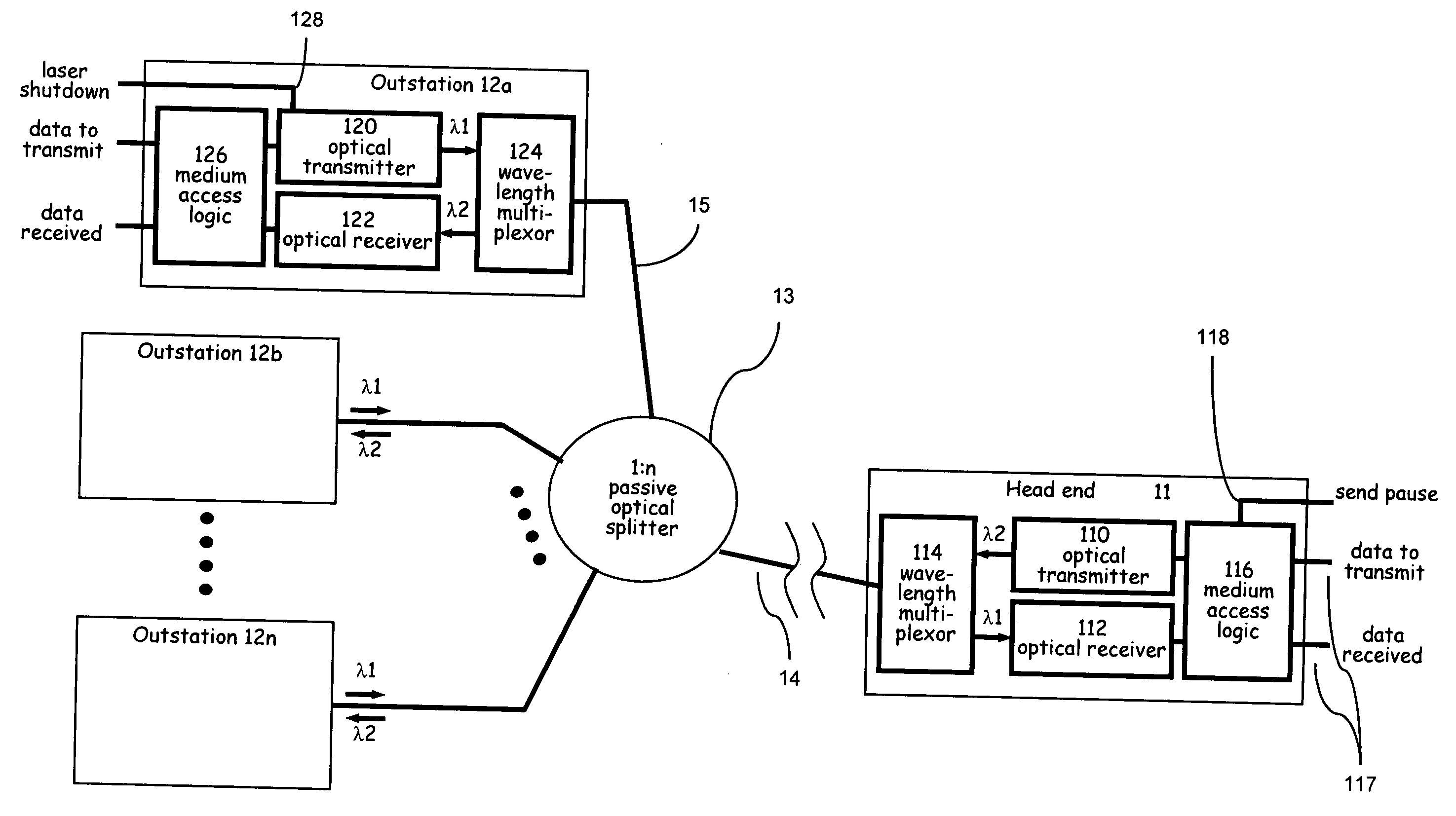
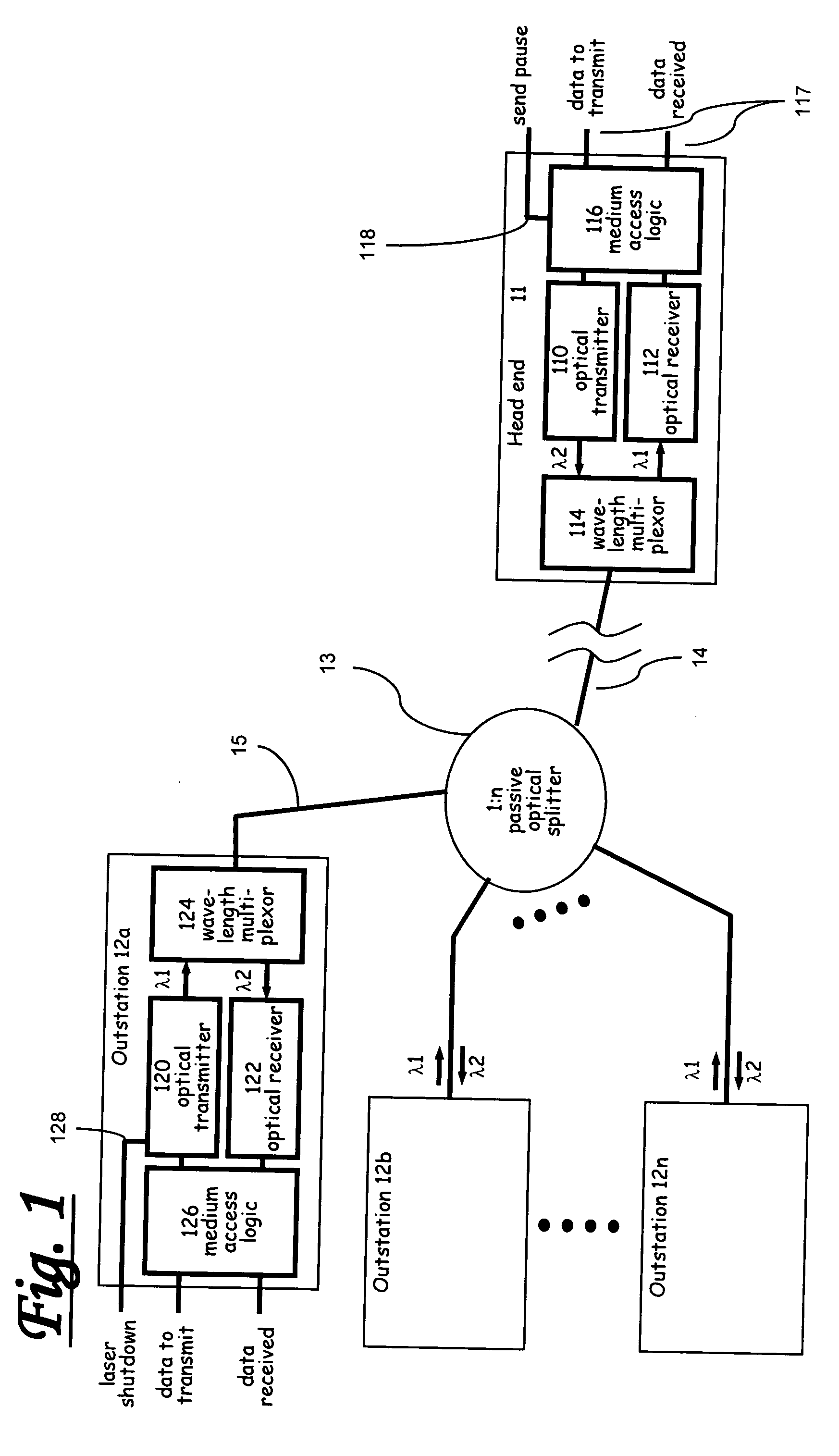
[0082] Referring first to FIG. 1, this shows in schematic form an exemplary FTTH access network in which a head end 11 is connected to a number of customer terminals or outstations 12a-12n through a 1:n passive optical splitter 13 via respective optical fibre paths 14 and 15. Typically, the distance from the head end to the splitter is up to around 5 km. The distance between any two outstations is assumed to be relatively small, typically about 500 m. The splitter 13 is located at a convenient point in the street and requires no power supply. In the system illustrated, downstream and upstream traffic use the same fibres and splitter, but each direction uses a different optical wavelength. Optionally, the network may use separate fibres and splitters for each direction of transmission.

[0083] As shown in FIG. 1, the head end 11 comprises an optical transmitter 110, typically a laser, operating at a first wavelength λ1, and an optical receiver 112 operating at a second wavelength λ2. ...


PUM


Abstract

A communications network (e.g. fibre to the home (FTTH) or wireless) comprises a head end, to which outstations are coupled via a shared point-to-multipoint medium. The head end is arranged to transmit downstream to the outstations a sequence of frames comprising data frames and command frames. The command frames marshal control of upstream transmissions from the outstations. A first downstream command frame directed to a specific outstation indicates the beginning of a timeslot, and also indicates the timeslot duration (including an indefinite duration). Where the duration is indefinite, a second command frame directed to at least the same outstation indicates the end of the allotted time slot. Further methods are provided to optimise timeslot allocation, and to support addition and removal of outstations on the network.

Description

FIELD OF THE INVENTION [0001] The present invention relates to access networks and to methods of carrying traffic over such networks. BACKGROUND OF THE INVENTION [0002] Traditional access networks, servicing residential and small business customers have typically employed optical fibre transmissions to a head end from which customers are served via local distribution units. In the past, the final drop to the customer from the distribution point has comprised a pair copper loop. In many cases this copper loop has previously been installed for telephony purposes. [0003] More recently introduced systems employ optical transmission between the head end and the distribution point, and there is now a incentive to extend the optical transmission path to the customer so as to provide fibre to the home (FTTH). Such a configuration has the advantage of overcoming the severe bandwidth limitations of the copper loop by replacing that loop with a broadband optical path. [0004] In a typical passi...

Claims


Application Information

Patent Timeline
Patent Type & Authority Applications(United States)
IPC IPC(8): H04B7/212H04Q11/00
CPCH04Q11/0067H04Q2011/0088H04Q2011/0064
Inventor UNITT, BRIANGRANT, MICHAELTATE, CHRISTOPHERWALLACE, ANDREWALGIE, GLEN
Owner LOREAL SA
Why Eureka
Try Eureka