Propulsive force controlling apparatus, marine vessel maneuvering supporting system and marine vessel each including the propulsive force controlling apparatus, and propulsive force controlling method

a technology of propulsive force and controlling apparatus, which is applied in the direction of marine propulsion, special purpose vessels, vessel construction, etc., can solve the problems of difficult to accurately control the propulsive force, the above-mentioned propulsion system is not popular, and the engine speed cannot be reduced to a lower level

Active Publication Date: 2005-07-28
YAMAHA MOTOR CO LTD +1
View PDF7 Cites 34 Cited by
  • Summary
  • Abstract
  • Description
  • Claims
  • Application Information

AI Technical Summary

Benefits of technology

[0035] With this arrangement, the very low speed marine vessel running operation can easily be performed by inputting the target propulsive force.
[0036] A marine vessel according to one preferred embodiment of the present invention includes a hull, a propulsion system attached to the hull and including a motor, a propulsive force generating member which receives a torque from the motor to generate a propulsive force, a clutch mechanism which is switched between a coupling state which permits transmission of the torque from the motor to the propulsive force generating member and a decoupling state which prohibits the transmission of the torque from the motor to the propulsive force generating member, and a clutch actuator which actuates the clutch mechanism, and a marine vessel maneuvering supporting system having the aforementioned features. With this arrangement, even an unskilled operator can easily perform the very low speed marine vessel running operation.

Problems solved by technology

However, the aforementioned propulsion system is not popular because of its complicated structure and high costs.
However, slippage occurs between clutch disks in the half-coupling state, thereby making it difficult to accurately control a propulsive force by detecting the rotational speed of a drive shaft provided at a stage before the clutch.
However, it is impossible to reduce the engine speed to lower than an idling speed, making it impossible to perform the trolling operation at a very low speed.

Method used


Image

  • Propulsive force controlling apparatus, marine vessel maneuvering supporting system and marine vessel each including the propulsive force controlling apparatus, and propulsive force controlling method
  • Propulsive force controlling apparatus, marine vessel maneuvering supporting system and marine vessel each including the propulsive force controlling apparatus, and propulsive force controlling method
  • Propulsive force controlling apparatus, marine vessel maneuvering supporting system and marine vessel each including the propulsive force controlling apparatus, and propulsive force controlling method

Examples


Embodiment Construction

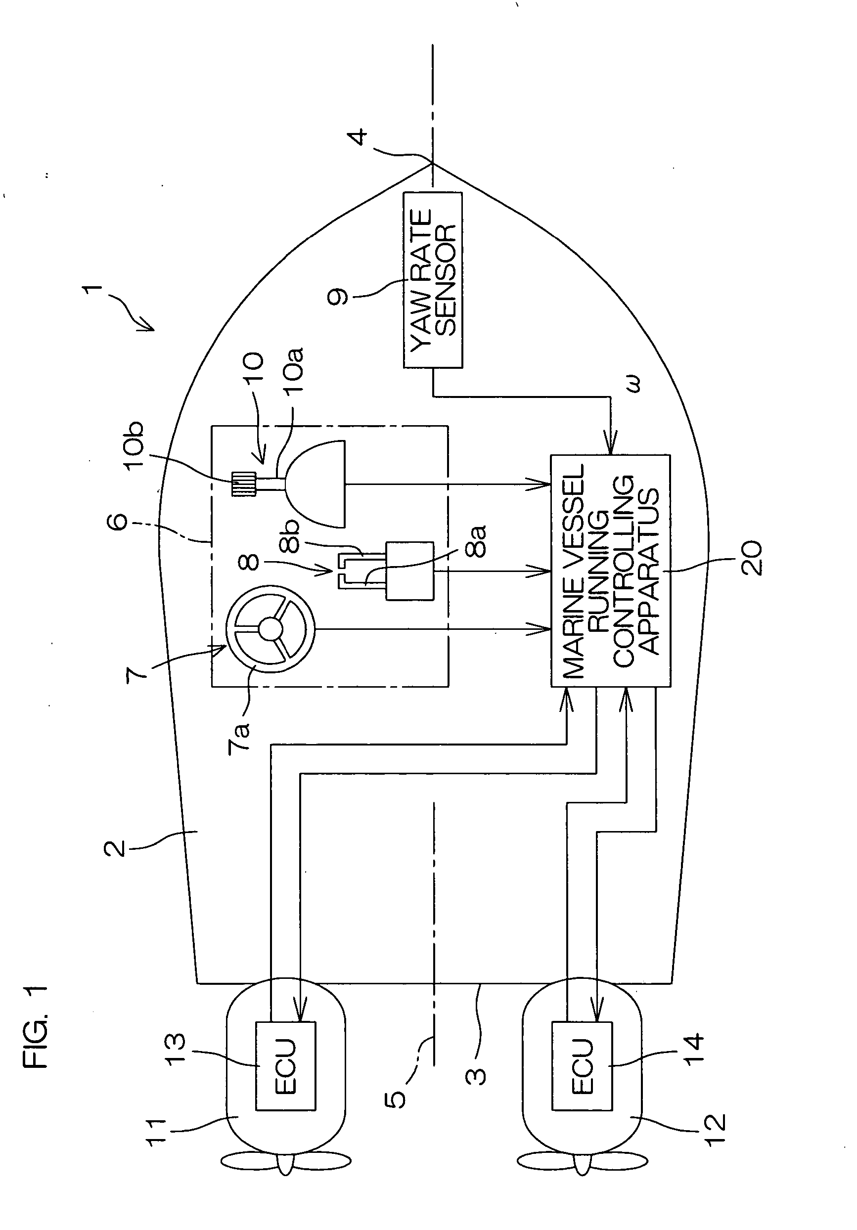
[0057]FIG. 1 is a schematic diagram illustrating a marine vessel 1 according to one preferred embodiment of the present invention. The marine vessel 1 is a relatively small-scale marine vessel, such as a cruiser or a boat, and includes a pair of outboard motors 11, 12 attached to a stern (transom) 3 of a hull 2. The outboard motors 11, 12 are positioned laterally symmetrically with respect to a center line 5 of the hull 2 extending through the stern 3 and a stem 4 of the hull 2. That is, the outboard motor 11 is attached to a rear port-side portion of the hull 2, while the outboard motor 12 is attached to a rear starboard-side portion of the hull 2. The outboard motor 11 and the outboard motor 12 will hereinafter be referred to as “port-side outboard motor 11” and “starboard-side outboard motor 12”, respectively, to differentiate therebetween. Electronic control units 13 and 14 (hereinafter referred to as “outboard motor ECU 13” and “outboard motor ECU 14”, respectively) are incorpo...


PUM


Abstract

A propulsive force controlling apparatus controls a propulsion system attached to a hull of a marine vessel. The propulsion system includes a motor, a propulsive force generating member which receives a torque from the motor to generate a propulsive force, a clutch mechanism which is switched between a coupling state which permits transmission of the torque from the motor to the propulsive force generating member with virtually no slippage and a decoupling state which prohibits the transmission of the torque from the motor to the propulsive force generating member, and a clutch actuator which actuates the clutch mechanism. The propulsive force controlling apparatus includes a target propulsive force acquiring section which acquires a target propulsive force to be generated by the propulsion system, and a clutch controlling section which controls (via intermittent coupling control, for example) the clutch actuator on the basis of the target propulsive force acquired by the target propulsive force acquiring section.

Description

BACKGROUND OF THE INVENTION [0001] 1. Field of the Invention [0002] The present invention relates to a propulsive force controlling apparatus which is applicable to a marine vessel having a propulsion system, a marine vessel maneuvering supporting system and a marine vessel each including the propulsive force controlling apparatus, and a propulsive force controlling method. [0003] 2. Description of the Related Art [0004] A propulsion system including an air-assist type engine and a multi-stage gear is conventionally used for causing a small-scale marine vessel (e.g., a boat) to run at a very low speed. The very low speed operation is required when a trolling operation is performed or the marine vessel is moved toward or away from a wharf. [0005] However, the aforementioned propulsion system is not popular because of its complicated structure and high costs. [0006] On the other hand, a hydraulic clutch controlling technique for a marine vessel engine is disclosed in Japanese Examined...

Claims


Application Information

Patent Timeline
Patent Type & Authority Applications(United States)
IPC IPC(8): B63H20/14B63H21/22B63H23/30
CPCB63H20/14B63H23/30B63H21/22B63H21/21
Inventor KAJI, HIROTAKAKANNO, ISAO
Owner YAMAHA MOTOR CO LTD
Why Eureka
Try Eureka