Circuit for supplying ear-microphone bias power for ear/microphone in mobile terminal

a mobile terminal and bias power technology, applied in the field of mobile terminals, can solve the problems of increasing standby power consumption, reducing standby time and battery life, and achieve the effect of reducing power consumption

Active Publication Date: 2005-07-28
SAMSUNG ELECTRONICS CO LTD
View PDF3 Cites 31 Cited by
  • Summary
  • Abstract
  • Description
  • Claims
  • Application Information

AI Technical Summary

Benefits of technology

[0020] Therefore, the present invention has been made in view of the above problem, and it is an object of the present invention to provide a circuit for supplying ear-microphone bias power for an ear / microphone in a mobile terminal, which makes it possible to reduce power consumption due to unnecessary ear-microphone bias power in a sleep mode when an ear / microphone is connected to the mobile terminal.

Problems solved by technology

Accordingly, compared to when the ear / microphone is not connected to the mobile terminal, standby power consumption increases when the ear / microphone is connected to the mobile terminal, thereby reducing the standby time and battery life.

Method used


Image

  • Circuit for supplying ear-microphone bias power for ear/microphone in mobile terminal
  • Circuit for supplying ear-microphone bias power for ear/microphone in mobile terminal
  • Circuit for supplying ear-microphone bias power for ear/microphone in mobile terminal

Examples


Embodiment Construction

[0025] Now, preferred embodiments of the present invention will be described in detail with reference to the annexed drawings. In the following description, a detailed description of known functions and configurations incorporated herein will be omitted to avoid making the subject matter of the present invention unclear.

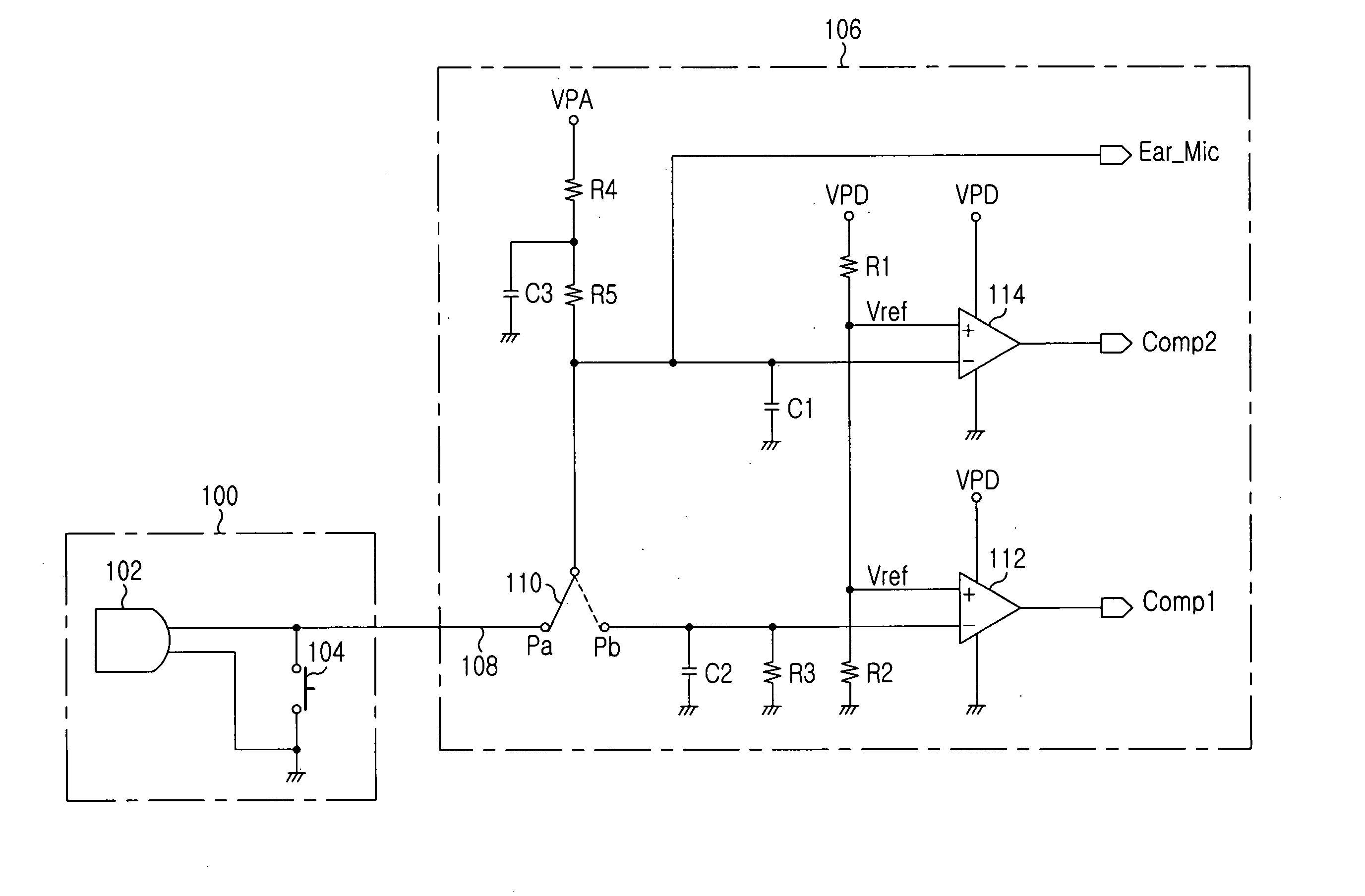
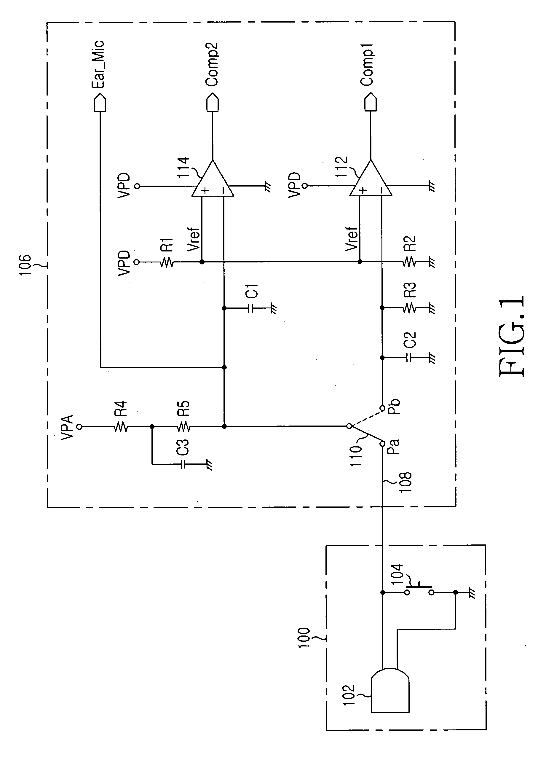
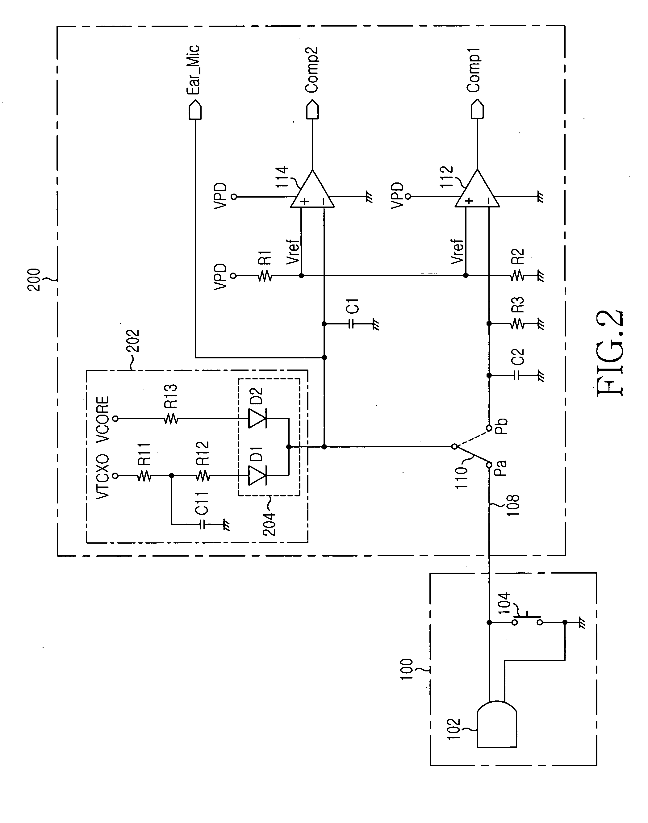
[0026]FIG. 2 is a circuit diagram showing an ear / microphone connection circuit 200 according to an embodiment of the present invention to which an ear-microphone 102 in an ear / microphone 100 is connected. As described above, the conventional ear / microphone connection circuit 106 of FIG. 1 drops the voltage of the supply power VPA through the resistors R4 and R5 and supplies the dropped voltage as ear-microphone bias power, which is also used as power for detecting the switching operation of the switch 104. The ear / microphone connection circuit 200 of FIG. 2 differs from the conventional ear / microphone connection circuit 106 of FIG. 1 in that a circuit 202 for supply...


PUM


Abstract

Disclosed is a circuit for supplying ear-microphone bias power in a mobile terminal that reduces power consumption due to unnecessary ear-microphone bias when the terminal is in a sleep mode with an ear / microphone being connected to the terminal through an ear-microphone line. The ear / microphone has a call switch connected to the ear-microphone line. The circuit receives first and second powers through first and second power input terminals, respectively. The first power is supplied when the terminal is not in the sleep mode, whereas the second power having a voltage lower than that of the first power is supplied also in the sleep mode. The circuit supplies ear-microphone bias power, based on the first power, to the ear-microphone line when not in the sleep mode, and supplies power for detecting a switching operation of the call switch, based on the second power, to the ear-microphone line in the sleep mode.

Description

PRIORITY [0001] This application claims priority to an application entitled “CIRCUIT FOR SUPPLYING EAR-MICROPHONE BIAS POWER FOR EAR / MICROPHONE IN MOBILE TERMINAL”, filed in the Korean Intellectual Property Office on Jan. 24, 2004 and assigned Serial No. 2004-4558, the contents of which are hereby incorporated by reference. BACKGROUND OF THE INVENTION [0002] 1. Field of the Invention [0003] The present invention relates to a mobile terminal, and more particularly to an ear / microphone connection circuit in a mobile terminal for connecting the mobile terminal with an ear / microphone that includes a call switch connected to an ear-microphone line. [0004] 2. Description of the Related Art [0005] An ear / microphone (i.e. an earphone / microphone), which has a call switch to receive, send or end a call, is widely used for hands free communication with a mobile terminal. The ear / microphone includes a speaker (i.e. an earphone) and a microphone, which are hereinafter referred to as an “ear-spea...

Claims


Application Information

Patent Timeline
Patent Type & Authority Applications(United States)
IPC IPC(8): H04B1/40H04B7/185H04M1/05H04M1/73
CPCH04M1/05Y02B60/50H04W52/0267Y02D30/70F16D65/10F16D65/12
Inventor JIN, HYUN-CHEOL
Owner SAMSUNG ELECTRONICS CO LTD
Why Eureka
Try Eureka